Q. I’m working on a new science building. As you have written on your web site, it’s gotten harder to use wheels. You wrote a while back about a proposed Addendum K to 62.1 – did that ever go anywhere?
As you might know, the Konvekta system is proposed as an alternate, yet it seems to me the wheel is still the gold standard. So I’m interested in whether you folks have given up on wheels in labs…
 Rick McGinley: No we haven’t, but many of our engineers have at least temporarily just because of the current ASHRAE standard. The standard has been amended and is awaiting final approval. We expect that within the next 6 months that obstacle would be gone. (See earlier post on this.)
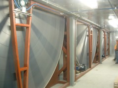
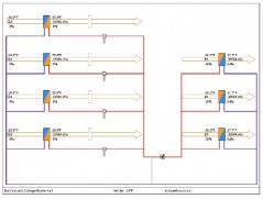
Ultimately whether the wheel is the best choice really comes down to what the lab design is, where the energy is produced and where it needs to go. If it was a very simple lab with just one AHU and one exhaust point then a wheel is the best choice. But if you have a lab with multiple AHU’s and EAHU’s in a network and also with some VAV or day/night staging there are frequent cases where the available exhaust energy needs to be transferred to a different supply zone. So from the standpoint of just the standalone energy recovery component the wheel is the most efficient device but multiple AHU’s with wheels serving different zones may not be the most efficient system.
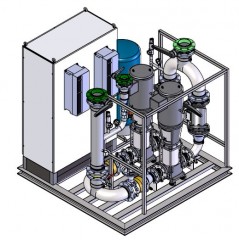
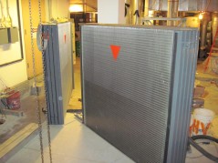
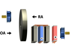
Konvekta Pumping Skid
With a Konvekta System you can gang all the systems through one pumping package and provide energy to where it is needed. Also with the Konvekta system heat from other waste heat sources can be injected in the glycol loop to provide complete heating for the system. In many cases we are also doing indirect evap cooling in the exhaust with a hi pressure water spray. This in combination with a precool/reheat coil loop at the cooling coil drops the incoming temp from 95db to 66db.
Related Blog Posts:
Ask Rick: Energy Recovery Wheel | Question on ANSI/ASHRAE Standard 62.1-2010
Ask Rick: Energy Recovery Wheels on Laboratory Fume Hood Exhaust?


 Is it required to add an R-Ring for every
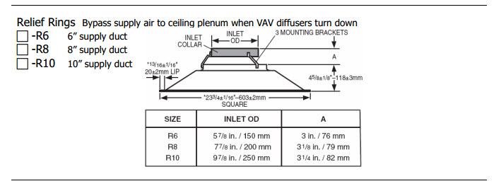

 The
The 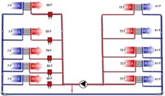 The Konvekta system is based on three core elements of a high-efficiency energy recovery system at their disposal:
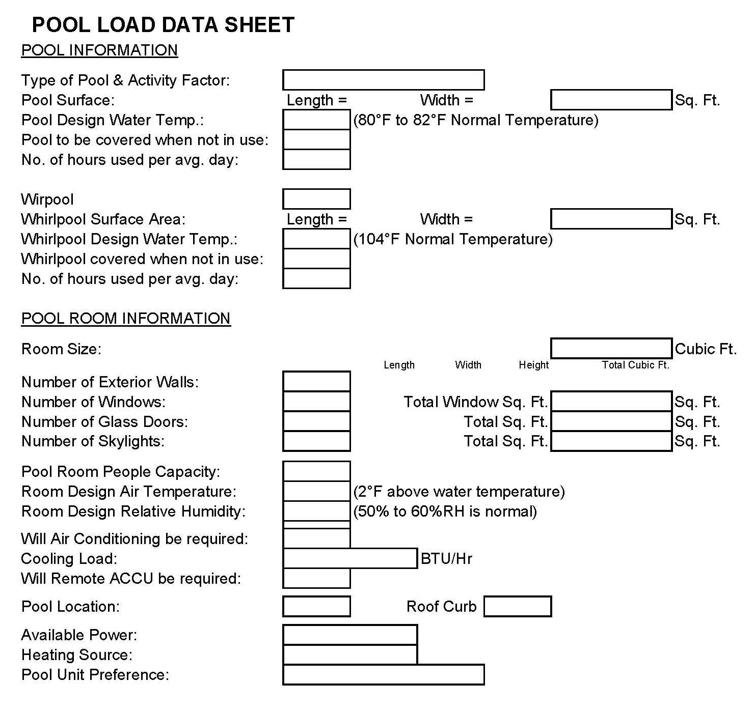
 We have tried to make this easy for designers. We have captured these questions on a very simple form:
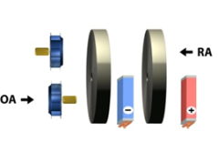
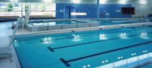 Pool dehumidification unit replacement is a large and growing business. Pool environments are very harsh and mechanical dehumidification systems have a typical lifespan of about 10 years. Building owners looking to replace equipment typically can provide model numbers, CFM capacities and like information. That is all good but it’s always important to start fresh on each project. We can never assume that the system was sized correctly the first time around.