Project Snapshot: Custom Field Erected AHU for University of Texas

Project Name:   University of Texas Tower Air Handling Unit Replacement

Univ. of Texas TowerLocation:   Austin, Texas

Project type, building type:   System overhaul, school (college, university)

Mechanical Engineer:   EEA Consulting Engineers

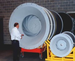
Equipment:  Custom Field Erected Air Handling

Manufacturer:  Air Enterprises (AEI)

Project duration:  1.5 years

Project completion date:   April 30, 2007


Engineering challenges

Location and space constraints for the new equipment:  
The tower was occupied and existing equipment remained in use for duration of the project.  There was limited access to the area where existing and new equipment were located.  This area is near the top of the tower, behind the walls that support the clock facings.

Time constraint for the switch over to the new system:
The two-week Christmas break between the fall and spring semesters provided the only period that the tower was not occupied.  The transition from the old air handling unit to the new one was scheduled for that period, which meant that all aspects of the project absolutely had to be completed and become fully operational during the break.

Solutions

Location and space constraints for the new equipment:
The solution was to remove a portion of the wall below the north clock facing to allow access.  A new equipment platform and stair system was constructed to support and access the new equipment in the tall void space inside the top of the tower.  A crane was used to lift the equipment and material into place as well as to remove and replace the 2,700-lb wall stones.

Time constraint for the switch over to the new system:
This entailed close coordination between the engineer, the owner, the consultants, and the contractor.  All parties committed early in the project to meet deadlines and to quickly address any issues that might arise.  As a result, the switch over proceeded smoothly and the tower reopened as scheduled.  Following the switch, final installation was completed.

Related Blog Post: 
Field Erected Air Handling Units | 4 Good Reasons to Assemble an Air Handling Unit On-Site

For More Information - askRick


Pumped Glycol Energy Recovery | Filtering Exhaust Air

Energy Recovery Filter Section

Energy Recovery Filter Section

Just skip the pre-filters in front of the exhaust side of the energy recovery device?   Is that wise?  We know that adding filters can impact costs:

  • cost to purchase pre-filters
  • labor to change
  • disposal costs
  • increased pressure drop

This question has been asked before and opinions have been offered by facility engineers.  Prefilters in Front of an Energy Recovery Device.  

Here is a look at the same question from the perspective of manufacturers of related equipment.    

This question was posed: 

We are recommending to an engineer that he leave filters off the face of a glycol coil on the exhaust side of a lab application.   He would like to hear the pro’s and con’s on why not to install filters.   How does your company answer this.


Rudolf Zaengerle, President of Konvekta USA Inc.  

It is not typical for engineers to recommend filtration in front of our coils.  With Konvekta coils, there are several reasons why filters are not mandatory:

  • Konvekta Pumped Glycol Coil
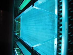
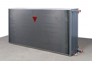
fins are flat and wide spaced: coil can be power-washed easily (once in 5-15 Years) – certainly less frequent than exchanging filters
  • lab exhaust is usually not high in particulate load (more so vapors that don’t ‘plug’ the coil)
  • in labs, our coil normally is epoxy-coated which is better in terms of ‘no dust adherence’ than no coating or almost any other coating


Paul A Tetley, Vice President & General Manager, Strobic Air Corporation

Typically all labs have pre-filters (30/30).  This is the default, unless they know that the primary air stream will be constantly clean and particulate free.  

UNH Strobic Fans

I fully agree that a typical class room lab in a university is exhausting conditioned air that is very clean and should not need any filtration prior to the coil, but it has always been specified.   I have seen sites as mentioned that took them out and never used them to save the pressure drop.

NIH Filtration guidelines say that the Design Engineer shall review the specific Program of Requirements to establish specific filtration criteria.  That’s the best bet for all applications.

There you have it.  Two industry experts weighing in on the subject.  I would agree that it really depends on the application.  On an animal lab you will need filtration, on a chemistry lab – probably not.  Best to look at it in a case by case basis but to always look at it.  There could be a significant savings passed up by just defaulting to filtering the air.

Related Blog Posts:
Ask Rick: Prefilters In Front Of An Energy Recovery Device?
Ask Rick: Custom Air Handling Units | Recommendations On Merv Filters

For More Information - askRick


Cost Savings with Passive Dehumidifier Heat Pipes

Puerto Rican-Based Pharmaceutical Facilities See Dramatic Energy Cost Savings with Passive Dehumidifier Heat Pipes

HPT - Puerto Rico
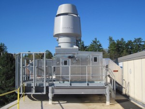
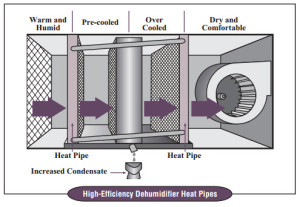
Pharmaceutical production is popular in many tropical locations because of regulatory, tax, and labor-cost benefits. Yet many of the benefits can be easily negated if a production facility doesn’t properly mitigate high humidity, an environmental feature that comes part and parcel with any tropical location.

Two Approaches to Controlling Humidity

  • Brute Force. The first approach to controlling humidity, uses so-called brute force – which means overcooling the air to reduce the humidity, and then (as counterproductive as it seems in tropical environments) reheating the air to achieve design temperatures.  Brute force is very costly and the overcool / reheat process is generally disallowed by ASHRAE Standard 90.1-2010
  • Green Approach. The second approach to humidity control – often called a green approach for the energy it saves – involves using a passive dehumidification system.  Passive dehumidification systems, such as dehumidifier heat pipes, are remarkably simple and easy to apply.   See related Blog post:   Wrap Around Heat Pipe | How Does A Wrap Around Heat Pipe Work?

Lets Look at the Numbers

HPT - Puerto Rico - AHU
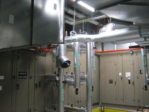
System:  10,000 CFM mixed-air system in San Juan, Puerto Rico. The system supplies constant 62°F dry bulb and 53°F dew point air

Brute Force Cost:  Annual cost of $53,900. (That figure is calculated in this way: Assuming 24/7, 50% OA, 75°F DB/50% RH Return Air, at .70 Kw/ton cooling and 70% heating system efficiencies, and $.15/Kwh, $1.50/therm.)

Green Approach:  For the same location, the passive dehumidifier heat pipe system had a cost of only $34,400, for a 36% annual savings.

Heat Pipe Technology – Two Comparison Cost Studies

Heat Pipe Technology has recently completed two retrofits in Puerto Rico using passive dehumidification heat pipe systems. One was for a pharmaceutical facility using 100% outside air, and one for a pharmaceutical facility using mixed air. In both cases, the green approach of passive dehumidifier heat pipes dramatically reduced energy costs over the brute force approach used in the facilities.  

Case 1:

Heat Pipe Technology System: Site Retrofit
HPT - Puerto Rico - HPT
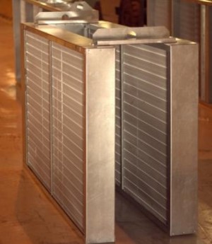
Application: 100% Outside Air
Location: San Juan, Puerto Rico

• 50,000 CFM Total Air:
• 525 fpm Air Velocity
• Hot Water Reheat 10°F
• Energy Cost:
     o Natural Gas $1.78 per therm
     o Electric Rate $0.19/kwh
• 24/7 operation; 365 days/year

Summary Results
• Precool Savings: $28,000
• Reheat Savings: $70,000
• Fan Penalty: $7,500
• Net Savings: $91,000
• Installation Cost Estimate: $88,000
• Simple Payback: 11.5 months

Case 2:

Heat Pipe Technology System: Site Retrofit
Wrap Around Heat Pipe
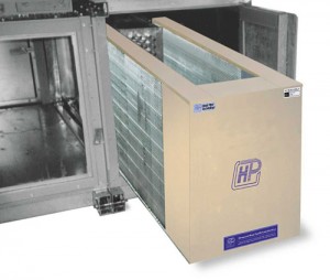
Application: Mixed Air
Location: San Juan, Puerto Rico

• 22,800 CFM of Total Air (1,800 CFM O/A, 21,000 CFM Re-circulated)
• 456 fpm Air Velocity
• Hot Water Reheat 8°F
• Energy Cost:
     o Natural Gas $2.0 per therm
     o Electric Rate $0.16/kwh
• 24/7 operation; 365 days/year
• Standard plant efficiencies

Summary Results:
• Precool Savings: $18,000
• Reheat Savings: $45,000
• Fan Penalty: $4,000
• Net Savings: $58,000
• Installation Cost Estimate: $50,000
• Simple Payback: 10.3 months

Related Blog Posts:   
5 Benefits Of Using Wrap Around Heat Pipes
Ask Rick: Wrap Around Heat Pipes | What Is A Typical Payback?

For More Information - askRick


Project Snapshot: Boston College – Air Handling Unit Refurbishment

Project Name: Boston College,  Higgins Hall
Location: Chestnut Hill, MA
Mechanical Engineer: BR + A
Manufacturer: AQUIS
Equipment: Custom Indoor Air Handling Unit Refurbishment 


Challenge

Boston College - Before
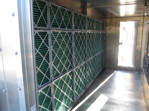
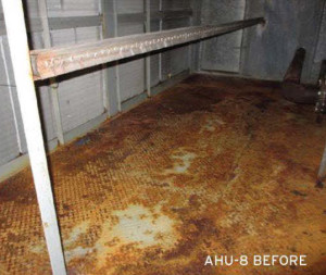
Higgins Hall is a science and research building on the main campus at Boston College, home to over 20,000  students in Chestnut Hill, Massachusetts. Their built-up air handling units, manufactured by Haakon Industries, had significant corrosion on the chamber floors and walls, resulting in holes that could potentially cause damaging water leaks in the building. Boston College selected AQUIS to refurbish the interior of six large units because they wanted to extend the life of the air handlers with a fully compliant and cost effective system.

Solution

Boston College - After
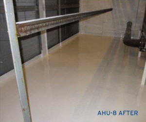
AQUIS installed its engineered coating systems on the chamber floors, walls, ceilings, and fan housings.

  • Chamber floors were completely sealed to eliminate potential water leaks and restore structure.
  • Installation was completed with minimal down time, zero VOCs, and did not require the removal of existing equipment.
  • The building’s AHUs are now fully compliant with NFPA 90A and the fire code (ASTM E84 25/50).
  • The system now has the benefit of an antimicrobial surface to eliminate bacterial/fungal growth.

Owner Comment

“Rather than incur the cost and delays of installing new air handlers or replacing floors, we did the research and found AQUIS.  Our system is now fully compliant for a fraction of the cost of replacement.”     Richard Hoy, Facilities Manager Research Zone,  Boston College

Related Blog Posts:
Air Handling Unit Refurbishment | A Viable Solution
5 Reasons To Refurbish An Existing Air Handling Unit

For More Information - askRick 


High Plume Dilution Fans | Handling System Effect

A mechanical engineer recently asked;  How do different types of fan blades handle the system effect?  Is there a best choice when it’s hard to determine system effect?  

I went to the expert on this one (no,  not Rick).  Paul Tetley,  Vice President & General Manager,  Strobic Air Corporation was kind enough to offer his opinion on this topic.  Paul knows more about fan construction than any other person I know (yes, even more than  Rick). 

UNH Strobic Fans
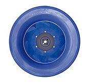
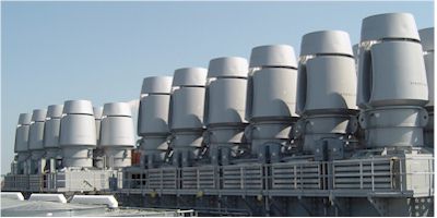
Fan published performance data is typically based on tests that have the air entering the inlet of the fan free of swirl and with uniform air flow patterns.  Any inlet condition that deviates from those designed and tested performance results has the possibility to produce a fan or system that has a de-rated performance.  The result in “as tested” ideal inlet conditions compared to “as installed” conditions are commonly known as system effect.  

To that end System effect factors need to be calculated to predict the installed performance of the fan or system that gives an allowance to compensate for poor (less than ideal) inlet conditions.  To complicate the calculation the system effect factor needed will vary based upon the velocity, and if the velocity is not uniform entering the fan it becomes very difficult to quantify the factor needed to calculate the de-ration in fan performance that will occur. 

Performance deviation in pressure, volume or energy usage is not the only thing that could be negatively impacted the fan.  Reduction in bearing life, increased sound levels, increased vibration levels and even blade failure could occur as a direct result.  Each fan type manufactured (axial, backward and forward curve, radial flow, cross flow and mixed flow) will react differently to system effect.  Below are just a few key factors to consider when evaluating the selection of a fan when looking at the impact of poor inlet conditions.

Paul Tetley - Strobic Air Corporation

Paul Tetley – Strobic Air Corporation

  • Axial fans usually have the flow through the impeller parallel to the shaft axis and have a hub that has either fixed pitch or adjustable wings attached.  The number one issue with a non uniform air flow entering this type of blade is that the amount of lift generated by the wing is based upon the velocity squared, and if the velocity is volumetrically different on the wings they will load and unload per each revolution.  Thus creating a large bending moment at the point of attachment to the hub and this will result in fatigue and catastrophic failure could occur.  
  • In backward and forward curve, Radial flow, cross flow fans the same effect occurs but because the flow is typically radial, instead of axial, the effect of the non uniform lift generated is now being transferred into a radial plane.  These blades have a back plate and in many cases a shroud that have the wings sandwiched between them that give it greater structural strength than the axial wing attachment point.  The fans are still seeing high axial buffeting that causes axial shock, the energy caused by this is then transmitted onto the drive shaft in the axial plane that will reduce the life of the bearings along with higher vibration levels.
  • A truly designed mixed flow impeller has both axial and radial flow characteristics and will be aerodynamically stable at any point of the pressure to volume curve. This then will generate an acceleration ratio through the blade passage ways that is constant regardless of volume and thus preventing axial shock and the above problems that that causes even though a reduced flow or pressure will occur.

Not all so called mixed flow fans are designed this way, the simple way to tell if a mixed flow fan is aero dynamically stable at all point of the P/V curve is to look at the curve and if the curve does not go all the way to the left (pressure axis) or has a dip towards that axis it is NOT a true mixed flow fan.

 Post content by Paul A Tetley  –  Vice President & General Manager,  Strobic Air Corporation

Related Blog Posts:  
High Plume Dilution Fans | What Is A High Plume Dilution Fan?
High Plume Dilution Lab Exhaust Fan | Mixed Flow Fan Curve

For More Information - askRick


UVC Lights – 5 FAQ’s

Steril-Aire UVC Install

Steril-Aire UVC Installation

There are a handful of questions that are commonly asked regarding UVC lights.  Here are the five that we see most often.

1.  What is UVC? 
Short-wave ultraviolet radiation, in the “C” band of 200 to 280 nanometers, has been used in a wide range of germicidal applications since the late 1800s to destroy bacteria, mold, yeast, and viruses. UV-C, or UVC, is often referred to as germicidal UV.  Ultraviolet light in this wavelength renders the organisms sterile. When organisms can no longer reproduce, they die.

2.  How does it work?
In general the UVC light is installed on the discharge side of the cooling coil and mounted so as to expose both the coil surface and the drain pan to as much light as possible. The light is normally positioned about a foot from the coil surface.  The “C” wavelength targets the DNA of microorganisms, causing cell death or making replication impossible. The UVC energy kills or inactivates microbes, eradicating surface biofilm.  Fixture UVC Emitters continuously clean coils, drain pans, plenums and ducts; improves product quality, shelf-life and yield in food processing plants.

3.  Can UVC save energy?
Yes. UVC devices degrade organic buildup in coils, keeping coils continuously clean. This lowers HVAC energy costs by improving heat transfer and increasing net cooling capacity. Steril-Aire has a Life Cycle Cost program that provides an excellent way to predict energy and operational savings.

4.  How often do the UVC lamps need to be changed?
The actual life of a UVC light is 10 – 12,000 hours. The useful life is 8-9,000 hours.   UV output is measured with a radiometer. Typically the light is changed annually — ideally in spring or early summer to provide optimal output during the peak air-conditioning season.

5.  Is UVC harmful?
UVC is only harmful under prolonged direct exposure – which is not generally an issue, since the devices are installed inside air conditioning equipment or are otherwise shielded to prevent exposure. Use of safety goggles and gloves is recommended as a precaution during installation to protect the eyes and skin.  UVC  light cannot pass through glass.  There is no harm to look through an air handling unit access window at UVC lighting. 

Related Manufacturer:
Steril-Aire

Related Blog Posts:
Ask Rick: What Is UVC?
Benefits Of UVC In Health Care Facilities
Ask Rick: UVC Emitters | How Will UVC Provide Cost Savings?

For More Information - askRick


Integrate VAV Diffusers Using BACnet

BACNet InternationalAcutherm, a manufacturer of components for heating and air conditioning systems, recently joined BACnet International as part of their work in integrating one of their signature products.  “Acutherm’s Therma-Fuser™ VAV System is designed to work cooperatively with a wide range of Building Automation System options,” stated Robert Kline LEED AP BD+C, Engineering Manager at Acutherm.  “The association with BACnet International and the resources it has to offer, such as the BACnet Test Lab, is an important element for integrating our VAV Diffusers with other building components.”

As a silver member, Acutherm joins over 80 of the leading building automation vendors in the world in pursuing advancement of BACnet as a communication protocol.

“Acutherm’s work in ensuring their products integrate using BACnet is a valued initiative,” stated Andy McMillan, President of BACnet International and Philips Teletrol.  “Their participation in BACnet International helps facilitate successful implementation of the BACnet Standard.”

EF-Brochure Image

Designed similarly to Acutherm’s independent models, the Acutherm EF-series Therma-Fuser diffusers recognize changes in room conditions and adjust control output for optimal performance.  The result is individual temperature control that precisely matches the comfort requirements of the room.

The EF provides more information about what’s happening in the space than any other VAV terminal because it monitors load, supply air temperature and flow at eachdiffuser.  Native BACnet BTL Listed or LonMark® compliance ensures that the EF will exchange data with products from other vendors on any LonWorks® or BACnet DDC building control network.  Interoperability with other control networks is easy using gateways by other manufacturers.

About BACnet International
BACnet International is an industry association that facilitates the successful use of the BACnet protocol in building automation and control systems through interoperability testing, educational programs and promotional activities.  The BACnet standard was developed by the American Society of Heating, Refrigerating and Air-Conditioning Engineers (ASHRAE) and has been made publicly available so that manufacturers can create interoperable systems of products.  BACnet International complements the work of the ASHRAE standards committee and BACnet-related interest groups around the world. BACnet International members include building owners, consulting engineers and facility managers, as well as companies involved in the design, manufacturing, installation, commissioning and maintenance of control equipment that uses BACnet for communication.

About Acutherm
Acutherm manufactures components for heating and air conditioning systems that make commercial buildings more comfortable, save energy, offer sustainability and can also reduce total installed costs.  Their components are called Therma-Fuser variable air volume (VAV) diffusers.  They are used in VAV air conditioning systems which, instead of varying the temperature of the cooling air, vary the amount of the cooling air to maintain even room temperatures.

Available Resources:
Acutherm Therma-Fuser EF Brochure
Acutherm Building Automation System Guide

Related Blog Posts:
Energy Saving VAV Diffusers | 6 Options For Building Automation Systems
VAV Diffusers | Providing Better Individual Temperature Control

For More Information - askRick


Composite Wheel Technology | A Good Idea

Composite Fan Wheel

Composite Fan Wheel

Composite material design has been the hot topic in new construction.  We recently visited one of our manufacturers.  They shared a new fan wheel design from Ziehl-Abegg.  This is a design that will begin to take center stage in the HVAC design industry.  

Composite Fan wheels are a great idea.  These are key advantages of using Composite Wheels:

  • Less Weight  –  up to 25% lighter
  • Very Stable  –  minimal vibration isolation required
  • Corrosion Resistant  – accommodate a wide variety of applications 
  • Extremely Quiet  –  up to 5 dBA less sound output
  • Extremely Efficient –  up to 3% more efficient


For More Information - askRick


5 Benefits of Using Wrap Around Heat Pipes

Wrap Around Heat Pipe - DiagramThe wrap around heat pipe is a heat pipe wrapped around a cooling coil.  It consists of two sections, the pre-cool section placed before the cooling coil and the reheat section placed after the reheat coil.  The wrap around heat pipe eliminates the need for reheat and increases the dehumidifying capacity of an air conditioner concrete pads by as much as 91%.  The technology uses about 50% less energy than electric reheat systems (hopefully you aren’t considering these) and about 25% less energy than other types of reheat.

 5 Key Benefits of Using Wrap Around Heat Pipes


  1. Increase Moisture Removal of A/C Units.  The first section of the heat pipe module precools the entering air. This causes the approach temperature of the air to the cooling coil to be lower. The result is, that as the air leaves the cooling coil, it is colder with a lower dew point and with less moisture in it. Depending on the design of the heat pipes, the cooling coil can be made to extract over 100% more moisture than one without heat pipes.
  2. Dryer Supply Ducts.  After leaving the cooling coil, the air is reheated by the second heat pipe section. This lowers the relative humidity of the supply air. In a typical system, the relative humidity is lowered from nearly 100% leaving the cooling coil to approximately 70% leaving the second heat pipe section. This is in keeping with ASHRAE Standard 62-1989 which warns that if duct relative humidity exceeds 70%, fungal contamination can occur.
  3. Humidity Control.  Buildings frequently encounter serious humidity problems that need to be addressed. Buildings used for specific purposes like hospitals, certain food processing plants, and some manufacturing plants require humidity to be kept at a low level.   Wrap around heat pipes are usually the most efficient method of humidity control in these situations. By helping the A/C system remove more moisture from the air, the required humidity levels can be easily achieved.
  4. Energy Savings Through Passive Reheat.  Since heat pipes provide reheat by utilizing the heat from the entering air, there is no requirement for active reheat and there is no net heat added to the space. Using heat pipes to replace active reheat results in substantial savings. A payback of one year may be achieved when electric reheat is replaced with dehumidifier heat pipes. If you find a furnace repair contractor, you may save some additional cash.
  5. Equipment Savings Through Downsizing.  To cope with high humidity loads, the most frequently used technique is to oversize the air conditioning unit and then reheat the over-cooled air. This results in high operating cost as well as initial equipment cost. If dehumidifier heat pipes are used, over-sizing and active reheating can be avoided. With a chilled water system, wrap around heat pipes allow the designer not only to reduce the size of the cooling coil but also reduce the chilled water requirement, thus a smaller chiller unit can be used instead.

Related Blog Posts:
Wrap Around Heat Pipe | How Does A Wrap Around Heat Pipe Work?
Ask Rick: Control For Wrap Around Heat Pipes
Ask Rick: Wrap Around Heat Pipes | What Is A Typical Payback?

Related Content:
Inventions and Innovation Program | U.S. Department of Energy – High Efficiency Dehumidifier

For More Information - askRick


Ask Rick: High Plume Dilution Fans | Control with VFD’s

Q.  I have a client with 6 Strobic Air fans. They operate only 1 on a VFD with another on VFD stand-by. The other 4 run at full speed. It appears to work fine so why should all fans be needed to ramp up and down together ? Thanks

A.  If fans are on a common plenum,  the air flow to each fan needs to be symmetrical to prevent system effect at the inlet of the fans.   If one fan over-powers the fan or fans at either side it will have a negative effect on the vena contra and disrupt the air flow patterns into the lower flow fan or fans. The amount of disruption is dependent on the volumetric differential.  The system may operate as intended but will not be as efficient.  
Paul Tetley   Vice President & General Manager, Strobic Air Corporation

Strobic AirThe system will work as per your description.  It just won’t be as efficient.  The size of the plenum would determine how much system effect would impact the design.  The larger the plenum and slower the velocity the less efficiency loss would be experienced.  

The most optimal system design uses variable frequency drives on all fans.  The fans modulate up and down together,  typically controlling for a static pressure set-point in the duct-work.

Related Blog Posts:
Ask Rick: High Plume Dilution Fans | Adding VFDs To Existing System
High Plume Dilution Fans | Introducing the Strobic Air Smart Fan Control System
Ask Rick: Strobic Air Smart Fan System | Controls Integration

 For More Information - askRick