VAV Diffusers | 5 Reasons why each Therma-Fuser has a Thermostat

Each Therma-Fuser VAV Diffuser has it’s own separate thermostat.  Each acts as an individual zone of control. 

Why a Thermostat is in each Therma-Fuser and not on the wall?

  1. Acutherm Therma-Fuser

    Acutherm Therma-Fuser

    Space temperature set points can be personalized to satisfy each occupant.
  2. Personalized temperature selections of the occupant remain set because the adjustment is out of the way from tampering by any visitor or passerby. 
  3. Average space temperature at both high and low air flow is better sensed at the Therma-Fuser location.   A wall thermostat typically does a poor job sensing the average room temperature. 
  4. Open office can be zoned without creating walls on which to locate thermostats. 
  5. Decisions about who has the thermostat and who goes either hot or cold are eliminated.

Therma-Fusers are made by Acutherm,  a US based company in Hayward California. 

Related Blog Posts:
VAV Diffusers | Providing Better Individual Temperature Control

VAV Diffusers | New clever design for the Therma-Fuser.

High Plume Dilution Fans for Diesel Generator Exhaust

High Plume Dilution Fans for Diesel Generator Exhaust:  

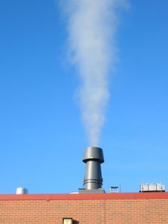
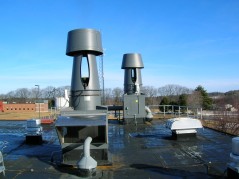
Strobic Air - Diesel Exhaust Fan

Strobic Air - Diesel Exhaust Fan

Emergency diesel generators are necessary evils for lots of facilities.  No one likes to have them around,  but they must be available to provide immediate backup electrical power in case of sudden power failure.

Diesel/electric generators must also meet critical performance requirements, but they can also create problems when tested (generally weekly without load and monthly under load).

The two major problems caused by diesel generators include possibilities of re-entraining their exhaust into the building’s ventilation system (or an adjacent building’s), and  unpleasant diesel exhaust odors in the neighborhood.  To prevent these problems we recommend high plume dilution fans from Strobic Air.

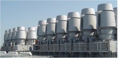
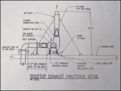
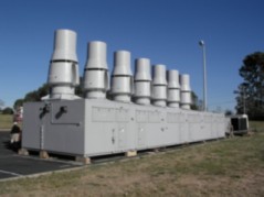
Strobic Air - Diesel Exhaust FanOver the years we have done dozens of Diesel Generator Exhaust fan applications with  Strobic Air Tri-Stack Fans (High Plume Dilution Fan).   Strobic Air has done a really nice job creating a solution to a problem for many facility owners.  A special High Temperature Tri-Stack fan is manufactured by Strobic Air.  These fans are available in rigid steel construction designed specifically for high temperature applications (such as emergency diesel generator, furnace or boiler room exhaust). Tri-Stack high temperature exhaust fans are UL certified for operation at 750°F for up to 2 hours without the need for outside air dilution, and incorporate chemical resistant high temperature coatings.   A brass rub ring on the inlet bell conforms to AMCA “C” spark resistance specifications.

Use the Strobic Air Online Selection Program for picking a fan.  Under the System Type,  choose  Diluted Hi Temp for the high temperature diesel fan.


Benefits of using high plume fan for diesel exhaust:

  • Ideal for assisting dispersion of odors into the neighborhood
  • High constant volume discharge avoids re-entrainment
  • Aspirated dilution up to 270% within the fan
  • High temperature reduction in the mixing box
  • Maintenance-free operation

Related Blog Posts:
High Plume Dilution Fans | What is a High Plume Dilution Fan?

Project Snapshot: High Plume Dilution Fans | Odor Control


Ask Rick: Custom Air Handling Units | Recommendations on Merv Filters

Q.  We are designing a new air handling unit for a lab.  What do you typically recommend for filter ratings?  We may be using energy recovery.

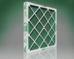
MERV 8 Filter

We recommend that you use a filter on either side of the energy recovery device.  Typically we use a Merv-8 on the supply side and a Merv-7 on the return side.   If you need final filters we would recommend Merv 14 for LEED jobs.  Otherwise filter selection is application specific.

Ashrae uses Merv Ratings for all filters.  Minimum Efficiency Reporting Values (MERV rate)

MERV ratings are used to rate the ability of an air filter to remove dust from the air as it passes through the filter.  The MERV scale ranges from 1 to 16, and measures a filter’s ability to remove particles from .30 to 10 microns in size (100 microns is about the thickness of a human hair). Filters with higher ratings not only remove more particles from the air, they also remove smaller particles.

Contact the safety consultants of the lockout tagout experts in industrial safety guidelines and the MERV Rating Chart below for more information about the difference in performance between filters with different MERV ratings.

MERV Rating Chart

ASHRAE Standard 52.2

ASHRAE Standard 52.1

Application Guidelines

MERV Rating

Particle Size Removal Efficiency

Dust-Spot Efficiency Percent

Particle Size and Typical Contaminant

Typical Applications

Typical Air Filter Type

0.3 to 1

0.3 to 1

0.3 to 1

20

≥ 99.999 in 0.1 – 0.2 μm particle size

< 0.3 μm
Virus (un attached)
Carbon Dust
Sea Salt
All combustion smoke
Electronics manufacturing
Pharmaceutical manufacturing
Carcinogenic materials
HEPA/ULPA Filters

19

≥ 99.999 in 0.3 μm particle size

18

≥ 99.99 in 0.3 μm particle size

17

≥ 99.97 in 0.3 μm particle size

16

> 95

> 95

> 95

0.3-1 μm
All bacteria
Droplet nuclei (sneeze)
Cooking oil
Most smoke
Insecticide dust
Most face powder
Most paint pigments
Superior commercial buildings
Hospital inpatient care
General surgery
Bag Filters – Non supported (flexible) microfine fiberglass or synthetic media, 12 to 36 inches deep.

Box filters – Rigid style cartridge, 6 to 12 inches deep.

15

85-95

> 90

> 90

> 95

14

75-85

> 90

> 90

90-95

13

< 75

> 90

> 90

80-90

12

> 80

> 90

70-75

1-3 μm
Legionella
Humidifier dust
Lead dust
Milled Flour
Auto emission particles
Nebulizer drops
Superior residential
Better commercial buildings
Hospital laboratories
Pleated filters – Extended surface with cotton or polyester media or both, 1 to 6 inches thick.

Box Filters – Rigid style cartridge, 6 to 12 inches deep.

11

65-80

> 85

60-65

10

50-65

> 85

50-55

9

< 50

> 85

40-45

8

> 70

30-35

3-10 μm
Mold
Spores
Dust mite body parts and droppings
Cat and dog dander
Hair spray
Fabric protector
Dusting aids
Pudding mix
Better residential
Commercial buildings
Industrial workspaces
Pleated filters – Extended surface with cotton or polyester media or both, 1 to 6 inches thick

Cartridge filters – Viscous cube or pocket filters

Throwaway – Synthetic media panel filters

7

50-70

25-30

6

35-50

< 20

5

20-35

< 20

4

< 20

< 20

> 10 μm
Pollen
Dust mites
Cockroach body parts and droppings
Spanish moss
Sanding dust
Spray paint dust
Textile fibers
Carpet fibers
Minimum filtration
Residential window air conditioners
Throwaway – Fiberglass or synthetic media panel, 1 inch thick

Washable – Aluminum mesh, foam rubber panel

Electrostatic – Self-charging (passive) woven polycarbonate panel

(Table Data Source – United States Environmental Protection Agency)


Related Blog Categories:
Air Handling Units
Energy Recovery

Does Coil Cleaning Save Energy?

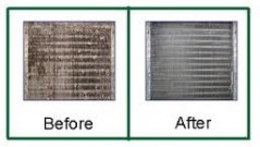
Does coil cleaning save energy?  This was the first question that we asked before agreeing to promote Steril-Aire as a manufacturer.  We knew that the technology worked;  that you could clean a coil to a nearly new condition by using UVC lights.  That we knew.  We also new that a clean coil would save energy.  But we didn’t know whether you could save  enough to make it worthwhile. 

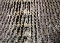
Dirty Cooling Coil Fins

Dirty Cooling Coil Fins

The short answer is yes,  coil cleaning does save energy and it is worthwhile.  I have included an article published in the November 2006 ASHRAE Journal;  “Coil Cleaning Saves Energy”.  This study looked at air handling units (AHUs) before and after coil cleaning to see what impacts coil cleaning had on energy savings.


Three key variables that added credibility to the study:

  1. The AHUs were large enough to provide substantial data (both units over 30,000 CFM). 
  2. The AHUs were constant volume (not easy to find these days).  It would have been difficult to quantify energy savings on Variable Air Volume (VAV) units.
  3. The weather data was constant during reporting periods.

The study looked at a huge building in downtown NYC.  See the following results and conclusions:

  • Cleaning the AHU SF-9 coil resulted in a decrease in the pressure drop across the coil, of approximately 14%. This resulted in a corresponding increase in airflow.
  • Cleaning the cooling coil in AHU SF-9 resulted in an increase of 25.3% tons of cooling (on prior 81 tons of cooling).  They estimated that 100 tons (352 kW) of cooling capacity would be added to the building once all four AHUs coils were cleaned.  (Building had a total of 1,800 [6330 kW] tons available capacity.)
  • Cleaning the cooling coil increased the thermal efficiency of the cooling coil 25% with respect to its ability to transfer its energy to its sensible loads (10% with respect to latent loads).
  • Cleaning the cooling coil would continue to save energy by decreasing the load on the chiller plant, and making the heat transfer of this loading more efficient. It reduced the time of multiple chiller operation and its associated pumps, cooling towers, chemical costs, wear and tear, etc.

It is worthwhile to note that the coils in these units were 30 years old and its last cleaning was nearly a year before the study.

Conclusion:  Good maintenance practices, including coil cleaning, can significantly improve energy efficiency (by as much as 10% to 15% as in this case).


Related Blog Posts:
Ask Rick: What is UVC?

Ask Rick: High Plume Dilution Fans | Adding VFDs to Existing System

Strobic AirQ.  We are considering conversion of constant speed Strobic fans (six fans on a common mixing plenum) into variable speed fans by adding VFD’s to satisfy the the plenum static pressure set point. What do you recommend to ensure that we do not run them below the required minimum plume height.


Over the years we have installed lot’s of Strobic Air Tri-Stack Fan systems without Variable Frequency Drives (VFD’s).  Most were installed on variable air volume lab applications.  Bypass dampers were incorporated to balance system load.  We are now looking to convert many to variable speed systems. 

First check to make sure that the motors are inverter duty.  Strobic Air has provided mostly Toshiba EQP III Premium Efficiency motors for the past ten years.  If the motor is not inverter duty then it will need to be replaced. 

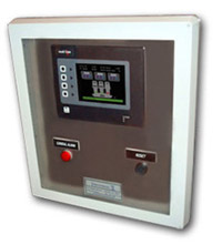
Strobic Air - Smart Fan System Screen

Smart Fan System Screen

Our first choice for controlling an existing system is the new Tri-Stack® Smart System.  We now design these into nearly all new multi-fan systems.  They provide several key advantages.

  • Controls fan speed to meet building demand while maintaining a minimum outlet velocity and stack height
  • Reduces sound levels at off-peak loading
  • Stages fan operation and rotates redundant fan
  • Can be retro-fit onto existing systems
  • Easy to use touch screen controls
  • Communicates with most building systems
  • Detects failures and activates backup fan
  • Controls isolation and bypass damper positions
  • Optional wind speed optimizer to adjust minimum outlet velocity based on wind speed and direction

The Tri-Stack® Smart System calculates the fan output from the Tri-Stack fan curve.  The direct drive motor makes this possible.  That allows for the use of static pressure sensing only.  Air flow sensing with pitot tubes in the hazardous air stream are not necessary. 

In lieu of the Smart System you can design your own control system.  You will need to measure duct static pressure and modulate the VFD’s to control for the system static pressure set-point.   The system will also need to measure airflow and maintain a minimum discharge velocity of 3000 fpm by staging fans on and off .  The VFD minimum speed should be set during system start-up.  Minimum fan flow can be determined from fan curves.  The sequence can get a little complicated as you need to control VFD’s, fan staging and bypass dampers.  Another reason to choose the factory supplied package.

Further questions on controlling High Plume Dilution Fans;  askRick?

Related Blog Posts:
High Plume Dilution Fans | Introducing the Strobic Air Smart Fan Control System
Ask Rick: Strobic Air Smart Fan System | Controls Integration

UVC Emitters | Fast Install Tower makes trial easy

Steril-Aire FIT  – Fast Install Tower 

This is an easy, economical way to try UVC Emitters on cooling coils.   We have a lot of customers that still aren’t convinced that UVC Emitters are viable.  We suggest that they try them.  Take a old dirty cooling coil, install the Steril-Aire FIT and wait a couple of months.  Bio-film and associated crud will be cleaned away.  Seeing is believing. 

More questions on UVC Emitters;  askRick?

Related Blog Posts:
Ask Rick: What is UVC?

Ask Rick: Bearing Life | What is L10?

Bearing Life

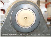
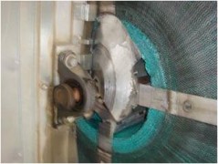
Thermotech Wheel Bearing

Wheel Bearing from Thermotech

Bearings are a critical component in all HVAC equipment.  Bearing life is usually expressed as the number of hours an individual bearing will operate before the first evidence of metal fatigue develops.  The usual life rating for industrial applications is called “L-10” life.  Simply put the L-10 life  is the number of hours in service that 90% of bearings will survive.  Or, conversely,  10% of bearings will have failed in the L-10 number of service hours.  

L10 life:   is the preferred term in specifying bearing life and is defined by The American Bearing Manufacturers Association (ABMA). 

L50 or average life:   is accepted as the bearing life associated with a 50% reliability, i.e., after a stated amount of time, only 50% of a group of identical bearings will not yet have developed metal fatigue.

L50 life equals five times the L10 life.  The following chart shows a comparison of L10 to L50 equivalents.                                 

Required L10 – Life Hours       Equivalent L50 (avg) Life Hours
20,000       100,000
40,000       200,000
80,000       400,000
100,000       500,000
200,000       1,000,000


No Guarantee

Failed Wheel Bearing

Failed Wheel Bearing

The bearing life rating is theoretical and based on statistics. Specifying a L10 life does not guarantee that the bearings will have a 90% reliability when installed in real world applications.  The calculation for Basic Rating Life assumes proper lubrication, no shock or vibration, perfect alignment, debris free environment and temperatures that are not extreme.   In the real world, none of these conditions are realistic and the “installed life” of the bearing will depend on the application and maintenance.

Further questions on Bearing Life;  askRick?


Energy Recovery Heat Pipes | 5 Advantages of using Heat Pipes for Air-To-Air Energy Recovery

We have choices in equipment that we can select for air to air energy recovery applications, we even have the best options for Geothermal Heating and Air systems.  Here are 5 advantages that Heat Pipes offer;
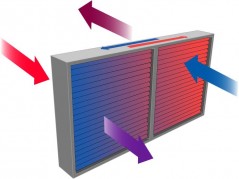
Heat PipeEnergy Recovery Heat Pipes Features

1.  Passive Operation
No energy input is required to operate the Heat Pipes. There are no moving parts.  When two air streams pass through the Heat Pipes, one air stream on the supply side and the other on exhaust side, the temperature difference between the two air streams heats and cools refrigerant.  The phase change of the refrigerant,  from a liquid to a vapor and back again, transfers energy from one side to the other.  It’s simple.

2.  Long Life
There is nothing in the Heat Pipes to wear out! The Heat Pipes are passive. They have no moving parts. To guard against corrosion, the Heat Pipes can be ordered with a protective coating. The Heat Pipes are fabricated with a multitude of charged circuits. Under normal operations, there is no reason for these ever to leak.  If one of the many circuits did leak there would be little impact on performance as other circuits would still function.
Heat Pipe Eneegy Recovery3.  Isolated Air Streams
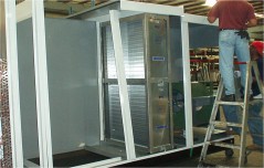
Dividing partitions to separate the two air streams can be easily added to Heat Recovery Heat Pipes. The copper tubes carrying the Heat Pipe working fluid are expanded into the mating holes in the dividing plates assuring an excellent seal to prevent cross contamination.  This divider makes heat pipes a good choice in laboratory type applications,  where cross contamination is a concern.

4.  Minimum Maintenance
Since the Heat Pipes have no moving parts, the only maintenance recommended is periodic cleaning. A coil cleaner may be applied for this purpose just as for any cooling coil.

5. Flexible Size
Heat Recovery Heat Pipes from can take up less space than other heat recovery schemes. They can also be manufactured in custom sizes to fit nearly any application.  Heat pipes can also be compact in depth.  A six-row heat recovery heat pipe can be fabricated with a thickness of as little as 8 inches.

Further questions on heat pipes;  askRick?

Related Blog Posts:
Heat Pipe for HVAC Systems | Heat Pipe Theory
Wrap Around Heat Pipe | How does a Wrap Around Heat Pipe work?

Visit Heat Pipe Technology for further information.
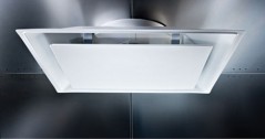
Ask Rick: Labratory Exhaust Fans | When should you manifold laboratory exhausts?

Q.  When should you manifold laboratory exhausts?

Typical Lab Exhaust Fan Set

Typical Individual Lab Exhaust Fan Set

We have been asked this questions countless times through the years.  In the past, public opinion held that you don’t know what lab chemicals are being work with so you don’t combine any lab exhaust.  All laboratory hoods were serviced by individual exhaust fans.  This was extremely expensive both in first cost and in operational costs.  Maintenance costs were very high.

When Strobic Air first introduced the Tri-Stack fan in 1986 nearly all systems were single fan systems.   Now nearly all systems are manifolded systems.  

Manifolding fume hood exhausts is recommended for all types of hoods with the exception of radioisotopes and perchloric exhaust.  By combining the exhaust hoods, sufficient mass can be achieved to create sufficient momentum to break through the recirculation zone on the roof.  This creates a safer roof environment and significantly reduces re-entrainment.

Manifolding systems also offers the following advantages over single fan sets:

  • First Cost Savings
    Strobic Air High Plume Dilution Fans

    Strobic Air Manifolded Fan System

    • Lower Equipment Cost
    • Lower Install Cost
  • Operation Cost Savings
    • Lower Energy Costs
    • Lower Maintenance Cost
  • Energy Recovery is significantly easier to design and more cost effective  
  • Increased System Flexibility
  • Added System Redundancy

More questions on Manifolding Lab Exhaust Fans;  askRick?

Related Blog Posts: 
High Plume Dilution Fans | What is a High Plume Dilution Fan?
High Plume Dilution Fans | 3 Key Design Questions


Air Handling Units | Split Replacement Coils

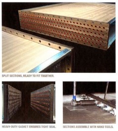
Split Replacement Coils

  • “I didn’t know these were available.” 
  • “Wish I had known about these sooner.” 
  • “What a great idea.,  this will save a lot of pain”
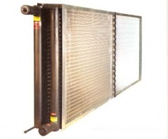
Split-Fit Coil from Aerofin

Split-Fit Coil from Aerofin

All comments that we have heard from building owners after showing them split coils.

Replacing large water coils in air handling units is never easy.  It’s even more difficult and expensive when equipment space is restricted (most of the time).  These Split-Fit coils from Aerofin are slick.  Long coils can be divided into smaller sections for field joining in the unit.  They are factory assembled and tested to ensure leak tight service in the field.

Split-Fit coils are available for both heating and cooling coils that have a maximum operating pressure of 100 psig and a maximum operating temperature of 160F.  The following ranges are available:

  • Fin Height:       12 to 54 inches
  • Fin Length:       as required to match existing coil
  • Rows:                 2 to 8
  • Circuit:              identical to original coil
  • Special Apps:   higher pressure/temperature designs are available

Split-Fit CoilSplit replacement coils offer a big advantage over having to create additional access space for coil replacements.  It also allows us to design tighter units knowing this is available for future coil pulls.

Questions on Split Replacement Coils;  askRick?

Related Blog Posts:
Ask Rick: When do you use a Desaturation Coil?
Custom Air Handling Unit Design | Desaturation Cooling Coil