5 Reasons to Consider a Composite Air Handling Unit

I cycle quite a bit.  I average about 2,000 miles a year.  Around the office that hardly counts as two workmates easily double that each year.  We ride a lot and we like bicycles.

Old Fuji DelRey - Steel

Old Fuji DelRey – Steel

When is the last time you bought a bicycle?  Things have changed a lot in 25 years.  I have posted a picture of a Fuji DelRey (circa 1988).  It’s a steel bike and weighs at least 30 lbs.  It was a great, solid bike in it’s time.  Today you can just barely sell it on eBay.

I have also posted a current picture of a Stradalli, with a carbon fiber frame.  It weighs less than 15 lbs.  The frame weight is a third the weight of a steel frame and equal in strength.

We embrace composite technology for home construction, aviation, ship building, cars and boats, bridge repair, and even ballistics protection.  And yes – bicycles.

So why not Air Handling Unit construction?  Why aren’t more companies making composite panel units here in North America?  They make composite units in Europe, India and China.  Here in the US we are now using a lot of aluminum units when providing residential air conditioning services .  They are lighter and last forever.  Composite materials are the next logical step for our Air Handling Units.

Stradalli - Composite

Stradalli – Carbon Fiber

Annexair has recently developed a composite panel Air Handling Unit.  Here are five major reasons that composite units make sense:

  • Unit weight is 30-40 % lighter than steel
  • Lifetime unit casing warranty against corrosion
  • No through metal, true thermal-break construction
  • No rusting & sweating, ever.
  • Cost is comparable to steel

It’s pretty amazing that they can provide the advantages of a composite panel system at the same price as a steel unit.  That makes the new technology a real bargain.

Annexair Composite Unit

Annexair Composite Unit

Annexair – Composite Flyer

Questions on Composite Panel Air Handling Units:

askRick Button


Ask Rick: Prefilters in Front of an Energy Recovery Device?

Ask Rick:  We are working on a lab application and considering not using filters on the exhaust side in front of the energy recovery device.   I would like to hear the pro’s and con’s on  why not to install filters. This will help us in designing future projects.  I would think the efficiency would fall off with a dirty coil pretty quickly.   Your thoughts would be appreciated. 

Energy Recovery Filter Section

Energy Recovery Filter Section

Just skip the pre-filters in front of the exhaust side of the energy recovery device?   Is that wise?  We know that adding filters impact costs:

  • cost to purchase pre-filters
  • labor to change
  • disposal costs
  • increased pressure drop

How do the actual economics shake out,  can we both maintain our device  and save money? 

We went to the source.  Here are actual opinions from respected engineers that work in our HVAC community.

“On our heat wheels we feel filters on the discharge are not necessary for lab or office environments.  We view it as an initial cost savings and a long term cost savings of energy and maintenance.  We are assuming that these indoor environments are relatively clean, and heat wheels are somewhat self-cleaning.

 With regard to a run around coil I’d probably not want filters for the cost reasons outlined above.  However, if the coils had a close fin spacing similar to a cooling coil, or the environment being conditioned were not clean like an office, I’d probably want the filters.”  Design Engineer  – University 


Exhaust Side Filter Section

Exhaust Side Filter Section

 “I looked at the filter sections of the units in one of our new buildings. They have not been changed since we moved into the building 3+ years ago, but they do need to be changed out. They have collected enough on the filters to prove that we are better off with them and that we would have had to clean them last year without the filters.    

It is a major undertaking when we have to remove the filters, which has to be worked out with our safety department.   Even with this said,  I feel I would leave in the filters for several reasons.

1) Glycol systems need all the help they can get with heat transfer. Without the filters they would lose efficiency during the years in service until it is cleaned again. 2) Putting on a Tyvek suit, gloves, booties and dust mask to remove the filters and place them into a plastic bag would be easier than the alternative.   Hiring a crew to come in with their PPE, spaying down the coils, and cleaning up the fluid is a terrible job.  Then we would need to determine how to dispose of it. 

I believe keeping a 10 to 12 row coil clean with filters is easier than trying to chemically clean it every 4 of five years.”  Facilities System Specialist – Pharmaceutical


 My opinion on this is that it depends on what kind of lab is it . . .

 If it is a clean lab, prefilters for an exhaust energy recovery coil make no sense.

 If it is a lab that has high efficiency filters on the air supply side, it probably makes no sense . . .

 But If it is a lab that creates dust or there is a possibility that debris can be drawn thru fume hoods or any other high velocity exhaust extraction it starts to make a little sense as inefficiencies caused by these pests can go on unnoticed for long periods of time.   Facilities Engineer – Research University


 We will be following up with further information on this topic in future posts.

Related Blog Posts:  Ask Rick: Custom Air Handling Units | Recommendations on Merv Filters

 For More Information - askRick


5 Reasons to Refurbish an Existing Air Handling Unit

Advantages of Air Handling Unit (AHU) Refurbishment Compared to Replacement:

  • Reduced cost compared to purchasing new units
  • More environmentally friendly by re-using existing equipment
  • Minimal equipment downtime
  • Existing services are typically unaltered
  • Minimal disruption to the building’s normal operation
AQUIS Before

Even if a building owner has done a good job maintaining their air handling unit, there comes a time when it needs to be replaced or completely refurbished. It is at this point, when the unit has begun to perform poorly and deteriorate, where maintenance costs begin to mount. 

Old, worn-out units also turn into energy hogs. Casing leakage alone can be as high as 10-15%. Inefficient constant volume fans, corroded coils and failing components add to the energy cost. 


AQUIS AfterCost Savings:  Where refurbishment is feasible,  this may be chosen as an option to replacement. With refurbishment there is a significant cost savings. Depending on the extent of the work,  the refurbished unit costs are typically only 20 to 30% of the cost of a replacement unit.

Environmentally Friendly:  Refurbishing existing equipment and extending it’s useful life is great sustainable solution.  Units can last an additional 15 to 20 years.   

Minimal Downtime:  Building owners want as little disruption and downtime as possible when dealing with air handling units. Downtime costs money, so a solution that will save money in the short and long term is essential.

Existing Services Unaltered:  By refurbishing an existing unit most of the services to that unit can remain intact. Duct work, piping and electrical service costs are significantly reduced.

Minimal Disruption:  In many cases sealing and re-pitching condensate pans, chamber floors and other surfaces is all that is needed to update an AHU. In those cases, only 6 – 8 hours of downtime is needed (typically in the evening and night) over a two day period. That’s it. The unit can run during the day between shifts. If additional equipment needs to be replaced or updated then schedules can be altered to make that happen with minimal disruption.

Related Blog Post:   Air Handling Unit Refurbishment | A Viable Solution

Case Study:  Aquis – Case Study – Boston College

Related manufacturers:  AQUIS

For More Information - askRick

Ask Rick: Bypass Dampers on Lab Exhaust Fan Systems

Q.  We are designing a lab exhaust fan system with multiple fans on a plenum.  We are using Strobic Air Fans.  We are using VFDs on the project.  Do we need bypass dampers?

BWH New StrobicsA.  We typically advise that bypass dampers only be used when necessary.  In a lot of applications where VFDs are used, bypass dampers are not necessary.  If the fans can turn down to the minimum design point and still maintain 3,000 FPM outlet velocity then we don’t need the dampers.  This will vary depending on the fan and number of fans selected.  Best just to look at the fan curves.

We build the control sequence to activate the bypass only when the VFDs have reached their minimum turn-down point.  That point can be roughly calculated in design and then adjusted during the balance of the system.  

In some cases we will provide the bypass damper as a backup in case a VFD will fail.  In this case we will still only provide one damper.

Note that when using VFD’s on a multiple fan system that, for best performance,  the fans need to be ramped up and down together.

Related Blog Posts: 
Ask Rick: Laboratory Exhaust Fans | When Should You Manifold Laboratory Exhausts?
Ask Rick: High Plume Dilution Fans | Adding VFDs To Existing System


Air Handling Unit Refurbishment | A Viable Solution

Problem:  Tired,  Aging Air Handling Units
 

We look at hundreds of Air Handling Units each year.  All types, all sizes and all conditions. Typically we are called in to assess problems or look at replacement options.  In some cases units are not in bad condition;  they don’t need to be replaced, just refurbished.  

I often thought that if we could re-pitch some drain pans and spray a good coating of Rhino Liner in the Air Handling Unit then 90% of the problem would be solved.  


Here’s a closer look at the problem:  

  • Aging Mechanical Equipment – Air handling units show indications of standing water, rust and corrosion.  Corrosion of the condensate pan caused by standing water quickly leads to damaging water leaks, increased maintenance, and eventually, premature equipment replacement.  The units are 
    structurally sound but leak air.
  • Fire Code Compliance – Coatings typically used to seal air handling units fail to comply with the requirements set forth by the National Fire Protection Association and other related bodies that govern the use of combustible materials within mechanical air handling equipment.
  • Indoor Air Quality – Mechanical air handling units exhibit indications of standing water in the condensate pans.  HVAC condensate pans with standing water are a frequent source of pathogenic biological agents.


The Rhino Liner idea was on the right track.  Too bad that stuff is not NFPA approved for Air Handling Units (good for trucks).  We did find something that is better suited and now widely used in our industry.


Solution:  Composite Coating to Seal Drain Pans, Sections and Other Compromised Surfaces.

There is a company named Aquis that supplys and installs a composite system designed to rejuvenate compromised surfaces on air handling units.   They provide a custom-engineered solution to fix tired, old air handling units.   Just what we were looking for.

Through sealing and re-pitching condensate pans, chamber floors and other surfaces, Aquis eliminates damaging water leaks and halts corrosion within the air handler. By eliminating standing water and providing a smooth, hygienic and antimicrobial surface, the growth of pathogenic biological agents is halted. 

The Aquis patent pending composite technology provides the only available solution that meets all regulatory requirements including NFPA 90A, ASHRAE 62.1, EPA, and others. 

We are now working with Aquis to provide the right solutions to tired, old air handling units.   It’s a part of sustainable design to make good, functioning equipment last longer.   We believe in that.

Case Study:  Aquis – Case Study – Boston College

Mfg. information:  Aquis AHU Refurbishment  

Related Blog Post:  5 Reasons to Refurbish an Existing Air Handling Unit

For More Information - askRick


Project Snapshot | Energy Recovery Unit – Tuck School at Dartmouth College

Project Name:     Whittemore Hall
Owner:     Tuck School of Business at Dartmouth College
Project Application:     Dormitory for Tuck Students
Mechanical Engineer:     BR+A
Equipment:     Energy Recovery Unit
Manufacturer:     Annexair
Size:     15,000 CFM


Whittemore Hall

Dartmouth Tuck - Whittemore Hall

Dartmouth Tuck - Whittemore Hall

The Tuck School of Business at Dartmouth College in New Hampshire was founded in 1900. Given this long-standing tradition in the study of economics and business administration, it is no surprise that the design of its newest graduate student residence would employ a state-of-the-art HVAC system to produce a healthy, comfortable living environment for its occupants, while delivering an annual return on investment that will eventually allow it to pay for itself.

Whittemore Hall is the focal point for residential and community life for both full time MBA students and executive program participants.  The four-story building consists of 60 private rooms, each with its own bath, 10 group study rooms, 3 conference rooms and a distance learning suite all organized around a central, common living room to foster a sense of community and teamwork.

The Invisible Hand

It was the college’s intention to make the building as energy efficient as possible.  To this end, the project was developed by Marc Rosenbaum, P.E. from Energysmiths and BR + A, the MEP consulting firm from Boston.  The overall concept called for an energy recovery air handling unit using an enthalpy wheel to supply 100% outside air to the bedrooms, while a more traditional VAV system served the public areas of the building.  The design of the HVAC system was further complimented by an extremely tight building envelope to reduce energy losses through air leakage, and by the use of triple glaze, low-e glass on the building’s many windows.  Based on prescriptive ventilation requirements dictated by ASHRAE 62-1999 it was judged that 14,700 CFM of outside air would be required in order to maintain an acceptable level of indoor air quality for the students.  The decision was also made to use the exhaust air coming from the bathrooms to maximize the latent recovery.

Significant Savings

The energy recovery air handling unit was supplied by Annexair, a Montreal based air handling unit manufacturer.  Every aspect of the energy recovery unit was constructed in accordance with the schools overall design philosophy.  “It was really nice to see a project like Whittemore, because it indicated to us that designers and specifiers are finally starting to realize that a truly energy efficient design requires a manufacturer that specializes in the thAnnexair Wheel Unitese types of packaged units.  We provided 2-inch double-wall construction, backward inclined fans with airfoil blades, premium efficiency motors, a steam preheat coil, a chilled water coil and of course a high performance energy recovery wheel.”  The benefit of this type of comfort-to-comfort application is that energy can be conserved during both the summer and winter months. Based on a bin analysis for Hanover, NH the use of the wheel results in a significant savings of $10,050 in annual heating and cooling costs for the facility.  One other important feature to note is the ability to significantly downsize the capacity of other HVAC components.  In this case, we were able to reduce the total cooling required by approximately 42 tons.


Promising Outlook

Results from past heating seasons have exceeded expectations.  Bo Peterson relates, “One winter morning, with an outdoor ambient of 5°F, the unit supplied 55°F air without opening the steam valve to the steam coil.”  Given that testimony, it is apparent that the college has made a wise investment.

Pumped Glycol Energy Recovery | Preliminary Design Questions

Preliminary Design Questions for a Pumped Glycol Energy Recovery System:

Dartmouth College Burke Hall - Konvekta System

Dartmouth Burke Hall - Konvekta System

Every energy recovery design starts with a list of questions that should be answered.  If these items are explored and discussed early on it makes for a significantly better design.  There are several distinct advantages in packaged pumped glycol systems from Konvekta.  A key system aspect is that you can take energy from multiple exhaust units and distribute it to multiple supply units.  This is a big part of what makes the system so efficient;  you take the energy from where it is and transfer it to where it is needed. 

Here are the key items that we look for in preliminary design of a Pumped Glycol Energy Recovery System:

  1. Project Name: 
  2. Project Location: 
  3. Supply Air
    • AHU Qty: 
    • CFM/ AHU:
    • Outside Air Percentage: 
    • Coil bank size – dimensions if possible, Face Velocity at minimum (500, 400 FPM): 
    • Desired LAT – DB/WB – Summer & Winter: 
    • If providing full heating through energy recovery coil:  Heat source – Hot water or steam, Temperatures available
  4. Exhaust Air
    Konvekta Pumping Skid - 3D

    Konvekta Pumping Skid

    • EAHU Qty: 
    • CFM/ EAHU:
    • Coil bank size – dimensions if possible, Face Velocity at minimum (500, 400 FPM)
    • Exhaust Air Temperatures – DB/WB: 
    • Exhaust quality – What is being exhausted?  Would the coils need a coating?
    • Adiabatic Cooling – would this be an option
  5. General Data
    • Schedule of occupancy  – night setbacks, partial occupancy, summer shutdowns, etc.
    • Utility Rates – average $/KWh, $/BTU heating, etc
    • Glycol – Ethylene or propylene

The more complete the information,  the better the analysis.  In this preliminary phase we like to come up with a payback analysis for the project.  That’s always a starting point with any energy recovery application.

See related Blog Posts on Konvekta:
Pumped Glycol Energy Recovery | What’s so special about Konvekta?
Pumped Glycol Energy Recovery | Konvekta High Performance Heat Exchanger Coil

Ask Rick: Pumped glycol energy recovery systems | Reasons for poor performance in traditional systems


Project Snapshot | High Plume Dilution Fans for Diesel Generator Exhaust

Project Name: Mass State Police Academy
Owner: State of Massachusetts
Project Application: Emergency Diesel Generator Re-entrainment Remediation
Mechanical Engineer: Shekar Associates, Inc.
Mechanical Contractor: Kleeberg Sheet Metal, Inc.
Equipment: “Tri-Stack” High Plume Dilution Fan
Manufacturer: Strobic Air
Size: TS3S150A12 – 14000cfm,  TS1S050A12 – 2100cfm
DAC Sales Engineer: David Goodman


Emergency Diesel GeneratorEmergency Diesel GeneratorThe Problem:  The new 911 Call center at the Massachusetts State Police Training Academy, in New Braintree,  MA, also housed 2 new Emergency Diesel generators and Diesel driven fire pump.  Lack of wind or wind gusts in the western direction was identified as responsible for diesel exhaust odor being entrained in the OA intakes of the air handlers.   This was obviously an unsafe condition for the 911 operators to work in so DAC Sales  was called to size Strobic Air fans.  Diesel exhaust is 950 deg F and higher and contains heavy un-burned particulate which reduces as engines warm up.

The Solution:   A single size TS-3 model, 15 HP,  Tri-Stack High Plume Dilution Fan was selected for the Emergency generators and a single TS-1 model,  5 HP,  was selected for the fire pump.  Each exhaust pipe discharged into a Stainless Steel (SS) rain hood on 1 side of mixing plenum.  Two of the remaining sides of the plenum were completely open with a SS screen.  This allowed for the large by-pass air volume needed to feed additional dilution air to  the exhaust plume.  Both fans provided a discharge velocity of 5000 + fpm and 35 + ft. of effective stack height in a 15 mph wind.   High temp coating and all steel parts were also part of the diesel package option.

Strobic Diesel FanStrobic Diesel Fan


Start-up Day: The Sat night prior to Monday Start-up, a drunk driver hit a pole and disrupted power to the Academy and surrounding communities.  The Emergency diesel started automatically and so did the Strobic fan.   The 2 ran for the weekend until power was restored.  This made for an easy DAC Start-up (already knowing the system was emergency tested). The photo below was taken immediately upon start-up.

Strobic Diesel FanWritten and Started by: David Goodman

Related Blog Posts:
High Plume Dilution Fans for Diesel Generator Exhaust
Diesel Generator Exhaust | Now Classified as a Carcinogenic to Humans
High Plume Dilution Fans | What is a High Plume Dilution Fan?


Ask Rick: Air Handling Units | Single point power connection?

Q.  We are in a disagreement over specification language.  In your opinion what does a “Single Point Power Connection” include?  Thanks,   Boston Engineer.


Electrical Panel

Good Question.  This comes up all the time. Depending on the application and circumstances “Single Point Power Connection” is defined in multiple ways.  Typically there are assumptions made, often times wrong, that lead to disagreement.

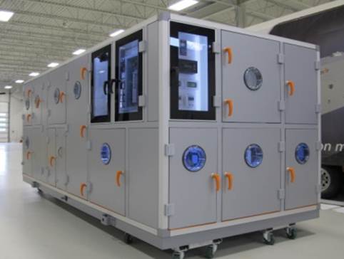
We view a single point power connection as main power to the Air Handling Unit.  This is the main “high voltage” connection brought to the unit. An electrical panel is provided to accept this connection.  From that point the manufacturer should own all downstream electrical components (VFDs, Fans, Energy Recovery Wheels, Humidifiers, Gas Heat, etc.) and wiring on the unit. 

Electrical PanelWhat the manufacturer does not own is controls and control wiring, unless this is clearly spelled out.  In many cases it is misconstrued by a user that a “Single Point Power Connection” includes all power and controls; everything.  Just hook up the unit with electrical and your set.  It’s not that way and it’s not that simple.

The biggest area of contention lies with who owns controls and what is included with that.  In many cases the manufacturer will supply actuators, mounted and wired, but not the full controls package.  That’s why it’s really important for the specifying engineer to call out exactly what is owned by the manufacturer (see example specification language below).

Our preference is to have the main power wiring brought to a panel as a single point of connection and have a separate, 120V, line run by others to cover service lighting and controls.  It makes sense to have service lighting separate from the main power.  That way when power is killed to the main disconnect there will be power still available to service lighting and controls.  That’s a lot safer.

Above all, it needs to be clearly spelled out in the specification and clearly communicated between all parties.  When this happens, the job usually runs very smoothly.

Here is a sample of what the electrical portion of the specification could look like:

21) ELECTRICAL

a)     All electrical and control components shall be wired into a NEMA4 electrical panel and shall be single point power connection.

b)    Electrical panel shall include:

                      i.        High & low voltage wiring with fuse protection
                     ii.        All variable frequency drives
                    iii.        Lockable non-fused disconnect switch
                    iv.        Laminated electrical, controls and refrigeration diagrams
                     v.        Air vent to evacuate excess heat
                    vi.        A separate wiring pipe chase for low voltage and high voltage
                   vii.        A drain shall be included in the electrical compartment

c)     Any motors controlled by a VFD shall be wired without the use of contactors and overloads.

d)    A UV resistant unit nameplate shall describe unit weight, all electrical requirements, such as FLA, MCA, MOP, and laminated one on the front door and one inside the electrical service compartment.

e)     All high voltage wiring shall be copper type tray cable, certified UL1277. Aluminum wiring is not acceptable. All high and low voltage connections shall have water tight connectors.

22) CONTROLS

a)     All controls including actuators to be by ATC contractor. 

 23) SERVICE POWER & LIGHTING

a)     GFI, lights and switches shall be factory installed and wired to a common junction box.  A separate power connection 120/1 shall be provided and powered by others.

b)    All lights shall be controlled by a single weatherproof light switch

c)     A marine light shall be provided in all accessible sections


Related Blog Post:   Energy Recovery Unit | Separate Control Panel Option

Feel free to add comments below.
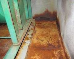
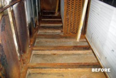
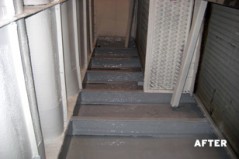
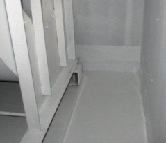
Custom Air Handling Units | Coil Selection Guidelines

I have included a collection of notes that we have pulled together over the years that guide us through typical coil selections for custom air handling units. 

Coils Basics:

  • Header Orientation –  Supply low leaving, return high entering
  • Coil Hand –  Face the entering air side of the coil to determine its hand connection. With air at your back which side (hand) are the headers on?
  • Plate Fin Type – Much more common, easier to clean
  • Spiral Fin Type – Less common.  Less pressure drop. Spiral Fin has advantage in steam heat coil as separate tubes can handle higher thermal expansion.
  • #Rows / Circuits = # of Passes


Coil Construction:

  • Tubes–  Copper is standard 
    • 5/8″ Tube O.D. is standard.  1/2″ Tube O.D. is more typical on DX
    • Tube thickness for water coils usually starts at  .020”, but we usually specify a .025” or .035”.   Belled ends allow for larger U-bends and less pressure drop.  We typically use them
  • Fins – Aluminum is standard  –  standard fin thickness .0075”, we sometimes use .0095” for hospitals/labs/high quality, .006 for lower cost

  • Casing– Galvanized is OK on Steam or HW Coils but Chilled Water (CW) coils are typically 16 gauge 304 stainless steel
    • typical casing is 1-1/2” leg but on most coils if spacing is tight can be 0.75” or 1”
  • Headers–  either Carbon Steel or Copper Headers are standard 
    • often use “non-ferrous headers” for cooling coils where there will a lot of moisture and condensation
    • MPT (Male Pipe Thread) is typical for coil connections
  • Coil Sizing – Fin Height
    • heating coils max FH of 60”  is max reasonable handling size in a shop
    • cooling coils – max FH for individual cooling coils with a drain pan expected to have significant condensation is 42” since condensation from upper part can cut airflow in bottom part
  • Coil Sizing – Fin Length
    • with no glycol, fin length can be whatever is needed up to 180”.  With glycol the WPD goes up significantly with higher FL so probably need to break big coils up into shorter length sections.
    • typical max coil width or length in an AHU is FL + 15” to outer dimensions of 2” wall AHU
  • Coatings – if a coil is going in unit within 3-5 miles of the ocean or in an area where corrosion might be a factor, need to include coating.  Electrofin is the best, good up to any number of rows, highly flexible so won’t chip easily. 

Selection Criteria:

  • Face Velocities
  Coil Type Allowable Velocity
  Hot Water (HW) 200 – 1200 FPM
  Steam 200 – 1200 FPM
  Chilled Water (CW) 200 – 550 FPM
  DX 200 – 550 FPM
    • Typical Hot Water Coil – 600 – 700 FPM
    • Typical Chilled Water Coil – 500 FPM
    • On a Cooling Coil – Air velocities above 500 fpm is the point where water droplets can leave the outer edge of the fin.  This is called moisture carry-over.   We design to avoid this.
  • Air Pressure Drop –  We typically design for less than an inch on all applications and look for a pressure drop near 1/2″.

  • Water Coil Pressure Drop –  25’ Water Pressure Drop (WPD) is about maximum – use bell ends to decrease pressure drop.
    • for HW coils, WPD up to 10ft is usually OK
    • for CHW coils, WPD up to 15-20ft is usually OK
  • Tube Velocity – stay below 8 ft/sec,  3 to 6 ft/sec is typical.  Number is higher with glycol
    • Optimize velocity through circuiting
  • Reynolds Flow Number –  under 2100 can cause laminar flow.  Can either change circuit (preferred) or add Turbulators (turbulators add pressure drop)
  • Max GPM – typically listed by connection sizes
  • Glycol –  Polypropylene (propylene glycol = PG) is more commonly used antifreeze
  • Fouling Factors –  Use 0 if you can.  Typical #’s are Ris (inside) .0005  Ros (outside) .001

Other Recommendations:

  • If space allows, making coil section larger to reduce velocity.  Moving to 300-400 FPM velocity adds a small % first cost but saves big in supply fan HP over life of unit. 
  • Glycol % has a drastic negative effect on transfer properties making GPM, coil and piping sizing go up. Always question unit design and operation if they request 40%
  • If coils are to be in a large VAV AHU application, velocity should not drop below 250 fpm or laminar air side will reduce effectiveness.  Face dampers may be needed to control air flow.

See manufacturer for further information on coils:  Aerofin