 Swegon teams with Astra Zeneca to create a showcase project.
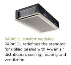
A PARASOL case study where the many advantages of four-way air distribution convinced AstraZeneca to go for our ground-breaking comfort modules instead of the conventional two-way air distribution of chilled beams.
New technology often requires two equally committed partners. The first is the developer of the technology and the second is the customer who, after thorough evaluation, is willing to give the technology a try.
An inspiring example of this kind of partnership is the recent collaboration between two international companies: Swegon and Astra Zeneca. Swegon is a global manufacturer of HVAC products (heating, ventilating and air conditioning), based in Kvänum, Sweden. AstraZeneca is a global biopharmaceutical company, based in London, The United Kingdom.
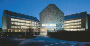
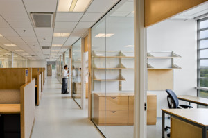
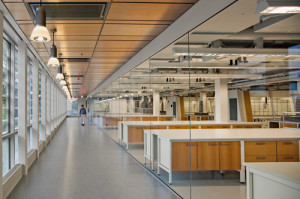
 The two companies began to collaborate in the US while AstraZeneca was designing an addition to their research campus in Waltham, Massachusetts. The facility plan combined offices and laboratories, presenting unique challenges for all aspects of mechanical system development. Among the most demanding was the need to heat and cool office workspaces while providing appropriate environmental control within adjacent research and development laboratories. “VAV”1 would have been a logical HVAC choice. An alternative to VAV cooling, chilled beam technology was already in the plan. AstraZeneca was familiar with the technology, having used “two-way blow” chilled beams throughout its five existing buildings in Waltham, primarily in offices. AstraZeneca had decided to continue with chilled beam technology in the new addition. The collaboration with Swegon was driven by AstraZeneca’s interest in the possibility of using fourway rather than two-way blow beams. Four-way offered the potential for cost reduction through the use of fewer beams, higher cooling output from a smaller ceiling footprint and the possibility of using the technology in select lab applications. AstraZeneca also had favorable experience with Swegon at its facilities in Sweden.
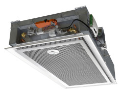
In chilled beam systems, chilled water from a central “chiller plant” travels through pipes into a heat exchanger – the chilled beam. Because water carries considerably more energy than air, chilled beams can produce the same cooling effect while using less energy and occupying much less space than that required for conventional ducted VAV air systems. An “active” installation uses the building’s air handling system to force air through the chilled beam and into a room. There are no moving parts near the office area being served which makes the system much quieter than conventional HVAC.
Pre-construction design of the new AstraZeneca building was well along when Swegon joined the project. Chilled beam technology was not widely used in the US and, as in existing AstraZeneca facilities, was a “two-way blow” system – meaning that air was distributed in two directions into offices from chilled beams in the ceiling. Two-way blow chilled beams had once again become the basis of design for office based cooling systems, now in the new AstraZeneca addition. However, Swegon’s newly developed “Parasol” four-way chilled beam system offered unique design alternatives for the AstraZeneca project.
Swegon’s Parasol product innovations provided a number of incentives and advantages for AstraZeneca to consider. Of primary interest to AstraZeneca was “four-way” blow: the distribution of air from all four sides of “comfort modules,” not just two. With Parasol four-way blow technology, the area available for heat exchange is increased significantly without having to dedicate additional ceiling area for the system. Air can be discharged from the Parasol comfort modules at a higher capacity, but lower velocity, for a more efficient mixture of air within the office environment. This is aided by four-way air diffusion which can be adjusted on each of the four sides of the module. The volume of air leaving each of the four sides can also be adjusted. The design of the Parasol outlet creates air turbulence that mixes conditioned air with room air before it reaches the occupied area of an office. The result is balanced comfort throughout the office area.
AstraZeneca conducted an extensive evaluation of the Parasol comfort module system. Any inclusion of the Parasol product would have to be justified by performance, cost and aesthetic benefits that more than offset the potential costs of building design modifications at the late planning stage. The potential switch to fourway blow was also considered to be a risk given the technology’s as-yet untried status in the US, a risk which had to be mitigated. The evaluation resulted in the following assessments for Parasol four-way blow vs. two way blow:
- From AstraZeneca experience in Sweden, Swegon’s two-way blow products were known to perform well and the company was considered a technology leader. This information, coupled with AstraZeneca Boston’s fourteen years of experience with chilled beam technology, paved the way for further investigation at this late stage of the project.
- Parasol four-way blow comfort modules provided superior air flow volume and adjustability over two-way. The Parasol 4 way spread would make it easier to adapt the HVAC when changing an office from open office planning to cells and back again.
- Chilled beams could be downsized for four-way, with corresponding energy savings.
- Fewer chilled beams would be needed with four-way. This resulted in savings to the ductwork design and also a reduction in the number of control valves and piping connections that would be needed.
- Four-way air flow adjustability would make it possible to use fewer modules in some offices, depending on total heat load.
- Lower velocity air flow with four-way would mean less noise and better acoustics.
- Four-way retained the advantages of chilled beam, including little to no maintenance requirements, no moving parts and corresponding high reliability.
- Reliable and efficient design will continue to support LEAN and energy saving initiatives, resulting in less resources in the operation and maintenance of the HVAC infrastructure.
- Aesthetically, the four-way comfort modules would be more acceptable than long two-way linear chilled beams.
- And in a future development, introduction of 4-way blow technology eventually resulted in AstraZeneca Boston’s revisiting the application of chilled beams in select laboratories.
The redesign cost estimate for adaptation of the Parasol four-way blow system into building plans was approximately $75,000. More than offsetting this was the estimated $300,000 savings to result from a switch to the Parasol four-way blow chilled beam product. Other considerations included the positive feedback regarding Swegon from AstraZeneca Sweden, the maturity of the Swegon chilled beam technology, and the schedule and delivery assurances from Swegon. After evaluation, the design change to Parasol was approved. Swegon personnel then participated in the new design solution by working directly with the AstraZeneca project team.
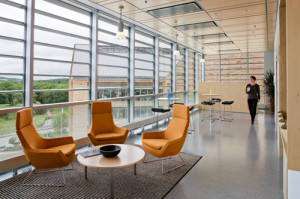
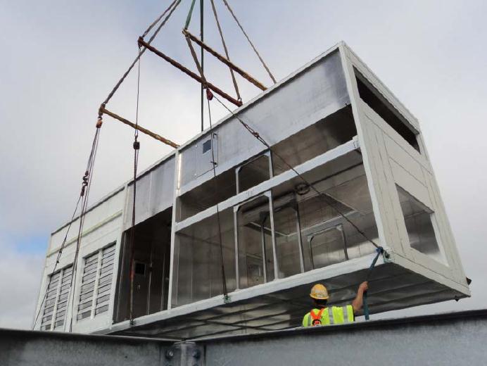
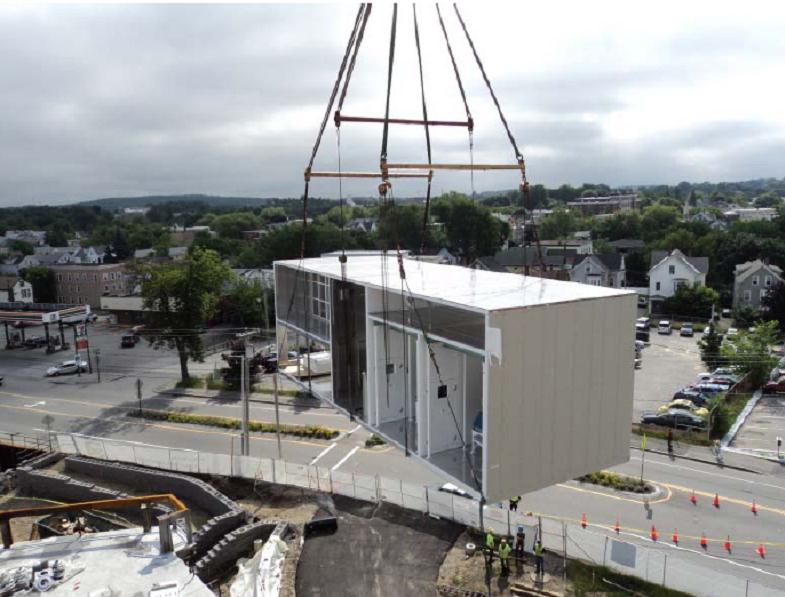
System installation went smoothly. Nearly 500 comfort modules were delivered on time, complete with custom paint and correctly oriented for the supply connections of each individual office. Wood ceilings required less intrusion than would have been necessary with two-way linear chilled beams. Savings resulted because available standard configurations of the 4-way beam (2×2 and 2×4) fit into the conventional ceiling grid designs.
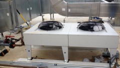
A brief description of the system features as implemented: The air handling system triple-filters air before bringing it into the building. A central chiller plant delivers 52F to 59F water, depending upon the season, to the mechanical penthouses in all buildings. Each penthouse (building) is equipped with a temperature controlled mixing valve station that maintains a 60F chilled water supply loop. The loop simply bleeds in and out supply and return chilled water, as needed, to maintain the 60F supply temperature. This eliminates the need for condensate drains at all chilled beams. Make-up air is introduced into the spaces through the chilled beam modules and is utilized to promote mixing of the recirculated and make-up air streams prior to entering the coil sections. The make-up air positively pressurizes the office environment above that of the adjacent laboratories and is transferred through grills located above the ceilings into the labs as make-up air, resulting in some additional energy savings. The optimized, balanced air movement provided by the Parasol comfort modules allows AstraZeneca to increase office occupancy from one to two persons if desired. Offices are controlled individually or in groups, determined by utilization.
Overall satisfaction with the Parasol solution is high, and the projected ongoing cost savings over next-best HVAC alternatives is 20%. The perceived risk of adopting the four-way blow technology alternative was mitigated by the realization of significantly enhanced airflow adjustability. The efficiency of the Parasol installation helps support AstraZeneca’s “lean initiative” and energy saving goals. The AstraZeneca project manager said, “The change from 2-way to 4-way technology proved to be beneficial in terms of cost and ceiling space allocation. The change to Swegon proved to be the right decision as they delivered the right product, on time. All of the beams were properly designated and set-up in the factory for location and orientation in addition to being staged to facilitate the sequence of installation. Project teams should not be reticent in exploring changes that can promote more efficient designs, both in terms of energy and project execution. Once the simplicity of the product was understood, the worries go away.”
Related Blog Posts:
Chilled Beams | Now with Demand Controlled VAV
Ask Rick: Chilled Beams | Are drain pans required?
Downloads: ADAPT Parasol Design Catalog


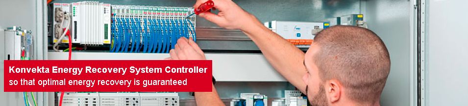
 Konvekta high performance energy recovery systems make a major contribution to reducing CO2 emissions and have a high rate of return on capital investment. Optimization of the system and trouble-free operation are critical. Installation imperfections, maintenance needs, software errors or incorrectly set control valves must be identified and corrected. To achieve this, continuous monitoring is essential so that maintenance needs and system malfunction are quickly detected, reported, and addressed. This guarantees a high level of system reliability and maximum energy recovery.
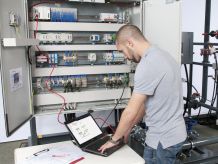
 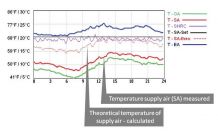 The calculations required to provide supply air at the desired temperature demands knowledge of the actual operating conditions, and performance maps of the energy recovery coils, pumps and valves. This data must be communicated to the system controller.
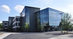 The
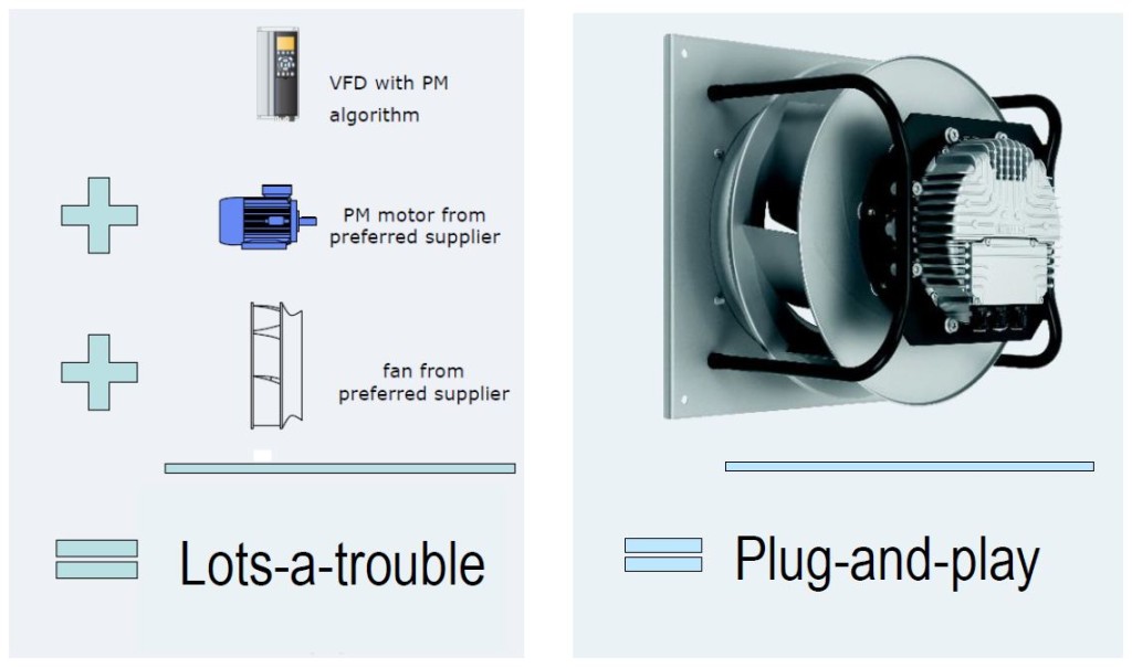
The 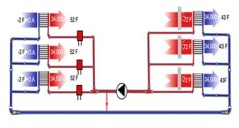 The Konvekta system is based on three core elements of a high-efficiency energy recovery system at their disposal:
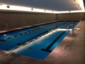
 In the Pool Dehumidification Unit Seresco provides a heat exchanger and a pumping package. In the heat exchanger the refrigerant loop dumps the rejected heat to a glycol loop. It is then pumped to the Fluid Cooler on the roof. Piping is PVC from the Pool Dehumidification Unit to the Fluid Cooler. The Fluid Cooler distance can be nearly anything (150 feet is not a problem).
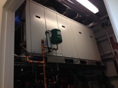 This application was also equipped with WebSentry, Seresco’s online monitoring, reporting and service optimization tool.
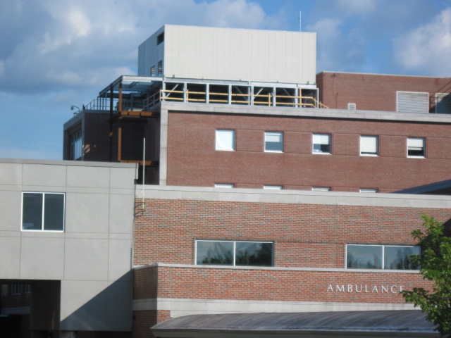

 Low Operating Temperatures: ECM motors’ high efficiency also means that the motors run “cool”, and dramatically reduce the amount of waste heat produced.
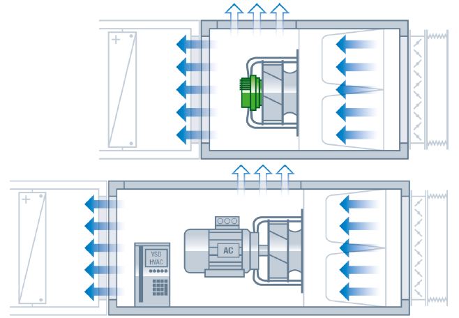


 Additionally, I’ve seen on units with HW/CW coils together that the freeze stat is on leaving side of CW coil. Int that case it’s basically the same as leaving air of the HW coil just 12” or so away. My experience is that freeze stat is never on the incoming side of the HW coil – always after the HW coil.