| Project Name: |
Brick Hospital, Brick, NJ |
| Owner: |
Ocean Medical Center, Brick, NJ |
| Project Application: |
Emergency Diesel Generator Re-entrainment Remediation |
| Equipment: |
“Tri-Stack” High Plume Dilution Fan |
| Manufacturer: |
Strobic Air |
Background:
 Emergency diesel generators are necessary evils at all hospitals. No one likes to have them around, but they must be available to provide immediate backup electrical power in case of sudden power failure.
When the facilities engineer at Brick Hospital, in Brick, NJ, discovered that emergency generator exhaust was being re-entrained into the fresh air intake ventilation system of the building’s West Wing, new ducting was constructed leading to the roof of the existing South Wing in an attempt to correct the problem.
The result was not favor-able. In fact, when it was relocated, the exhaust was also re-entrained into the South Wing’s ventilation air intakes, actually creating more of a problem than if it had been left where it was. “We were living with that problem for about seven years,” said the facilities engineer.
Results:
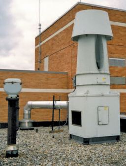
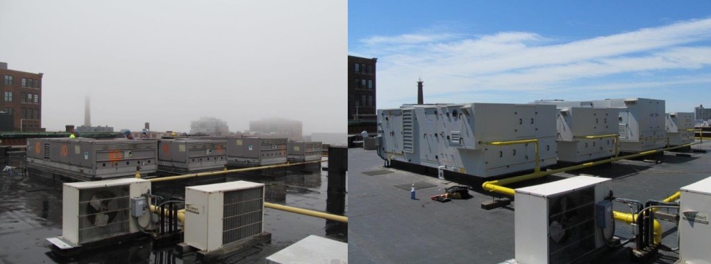
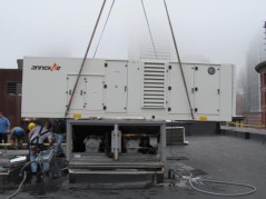
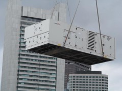
Eliminating the re-entrainment problem was Brick Hospital’s main concern. The facilities engineer contacted a leading consulting engineering firm in New York City who recommended that StrobicAir Tri-Stack Fans be mounted on the roof to serve the two generators. When dealing with re-entrainment problems, crosswinds can cause many issues. In this particular case, with a 10 MPH crosswind, the Tri-Stack fans – rated at 20 hp and 15 hp respectively, with the 20 hp fan operating at about 7600 CFM – are able to project the exhaust stream at a nozzle velocity of over 4,600 FPM, allowing it to rise to a height of approximately 65 feet above the roof-line, providing effective dissipation and preventing any possibility for re-entrainment.
In configuring this system, the consulting engineering firm terminated the existing flue pipes on the roofs of the South and West Wings, intercepting them and forming new transition sections to connect to the fans. A minimal amount of rein-forcing steel was added to the building’s roof framing structure. Each Tri-Stack fan was bolted to its curb, and each curb was bolted through the roof to the supplementary support steel. And because the Tri-Stack fans are precisely balanced and use direct drive motors, there was no need for additional vibration isolation, resulting in significant savings compared to most other fans in the industry. Brick Hospital’s facilities engineer was pleased. “The fans operated smoothly with no sensation of vibration below in the occupied spaces,” he stated. “And from an aesthetic stand-point, these fans are barely noticeable from the surrounding area. Thanks to their capabilities,there was no need for any tall flues or stacks.”
A secondary concern – the temperatures of the flue gases coming from the diesel generators are 840° F. – was also easily addressed by the Tri-Stack fans, which mix the flue gas with ambient air at a 560% dilution ratio, effectively providing about 43,000 CFM total at 186° F and eliminating the need for a high temperature nozzle. This saved the Brick Hospital extra costs by diluting the temperature low enough where a standard nozzle, made of fiberglass instead of stainless steel,was used.
The elimination of re-entrainment, the industry’slowest vibration standards, and economically diluting high flue gas temperatures left the Brick Hospital fully satisfied with their Tri-Stack fan systems.
Present Status:
15 years later, the Strobic Air Tri-Stack fans are still running and performing as promised, preventing re-entrainment, diluting the odor, and producing very little noise. The mixed flow impeller design, low vibration, and high dilution rate are key factors to the longevity and success of the Tri-Stack fan systems.

Mass. State Police Academy
Diesel Generator Exhaust Fan
Related Blog Posts:
High Plume Dilution Fans for Diesel Generator Exhaust
Diesel Generator Exhaust | Now Classified as a Carcinogenic to Humans
High Plume Dilution Fans | What is a High Plume Dilution Fan?


 Project scope:
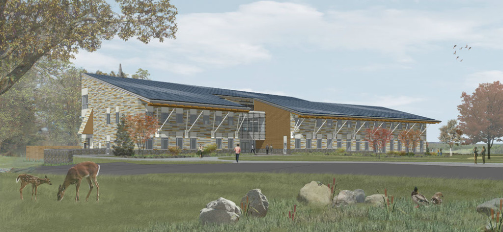
  The building features operable windows (large windows provide daylighting and views to 90% of living spaces) and individual airflow, with thermally-powered VAV system provided by Acutherm. The Therma-Fuser DDC Interoperable Diffusers meet the set comfort requirement of each space automatically and eliminate over heating and over cooling.
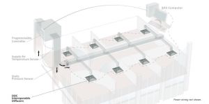
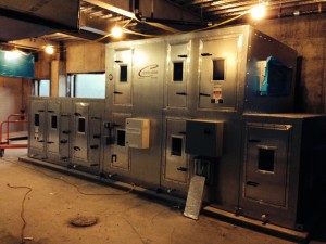

 Thermo-Composite panels shall be provided for the entire unit construction, including but not limited to, walls, doors, floors, roof, interior partitions, and electrical compartment. The frame shall consist of anodized extruded aluminum profiles which incorporates a thermally broken construction; welded together for reinforcement and insulated for superior thermal performance. Base structure shall be fully welded and have integral lifting lugs which can be removed once the unit is installed. All roof and side wall seams shall be positively sealed to prevent water and air leakage. Panels will be non-load bearing type.
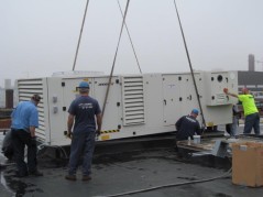 Unit shall have the entire exterior finished with a PVDF coating designed for UV resistance. Paint shall pass ASTM B117 3000-hour salt fog resistance test and ASTM D4585 3000-hour moisture condensation resistance test. In addition, paint must meet AAMA 620-02 standard for color, chalking, gloss retention, and abrasion resistance. The air handler unit casing shall be provided with a lifetime warranty against corrosion resistance under normal use.
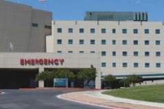 Hospitals provide an enormous opportunity for energy recovery due to their 24/7/365 operations. Energy from the exhaust air stream can be recovered in the winter and summer to precool or preheat supply air to the hospital and save a lot of energy dollars in the process. One key byproduct of energy recovery that must be avoided in hospitals is contamination of supply air with exhaust air. It is important that no odors or airborn pathogens be transferred into the supply air stream while energy is being recovered. Heat Pipe Technology provides the most reliable form of energy recovery without the threat of cross contamination.
 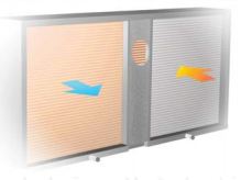 Heat Pipe Technology’s Energy Recovery Heat Pipes (HRMs) utilize the phase change of the working fluid, capture energy from the warmer air stream and transfer it to the cooler air stream. In colder climates such as Minnesota, the energy is transferred from the exhaust air stream to preheat the supply air stream. This reliable method has no moving parts, requires minimal maintenance, and is cross contamination proof
 In July 2010, one HRM was installed in the hospital. The warm exhaust energy was transferred to the cooler supply air stream, yielding immediate savings by preheating the ambient air. Since Heat Pipe Technology’s HRMs are cross contamination proof, no pollutants or airborn pathogens from the exhaust air stream can enter the supply air stream; therefore, the ventilation requirements are truly met and the indoor air quality of the hospital is maintained.

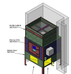 Overcoming Space Constraints: David Goodman was invited for a walk through by MIT HVAC Supervisor. The goal was to find and claim floor space and design a vertical cooling unit to fit it. An open corner directly straight ahead was accessible with only a single data rack to move. Quick measurements showed that a 4 ft X 4 ft Vertical unit could fit if built in modules with KD Knock – Down legs and drain pan.
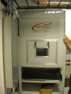 Unit Features: MIT chiller plant allows CW temp to rise in Winter making the coil selection very challenging for the team. The unit with ECM fans was capable of moving more air in winter months for more air turns if needed. Control panel contains On / Off switch and BMS Auto mode with relays to start/stop the new units OR the existing ceiling units. Panel mounted potentiometer allows for ECM fan speed to be set by balancer or adjusted as needed.