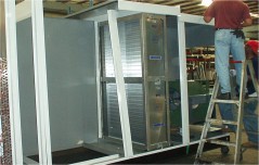
 Frost control for any energy recovery device here in New England is typical. This post looks at heat pipes. With a building Exhaust Air of 68°F and 50% relative humidity, with typical air flows, a 6 row Heat Pipe will begin to frost when the Outside Air temperature is somewhere between 0° to 10°F.
We will typically use face and bypass dampers around the supply side of the heat pipe to provide frost control. The following are the most popular sequences we use for control. The key is to use frost control as little as possible. Remember, the heat pipe is less efficient in the frost control mode.
Control Sequence 1
A dry bulb temperature sensor is installed on the leaving air side of the exhaust side of the heat pipe (see drawing). If leaving Exhaust Air (EA) temperature drops below a set point (typically 36°F) then we modulate actuators on the bypass and face dampers (located on the supply side of the heat pipe) to maintain the set point.
Control Sequence 2
Preferred Method: For more efficient control we would recommend using an enthalpy sensor in tandem with the EA dry bulb temperature sensor. When EA temp drops below the 36°F set point and the enthalpy sensor rises above 90% RH (adjustable) the supply air face and bypass dampers are modulated as needed to maintain the 36°F set point.
 Notes:
- Schools or other non-humidified buildings in New England can have extremely dry environments in the winter season, with typical relative humidity ranging from 20% to 30%. Return air at 72° / 20% RH has a Dew point temperature of 29°F. The bypass set point for buildings like this can be lowered to achieve a higher effectiveness for the heat pipe (or use Control Sequence 2)
- Sensor placement: A heat pipe does not have completely uniform temperatures across its face. The coldest return fluid in the liquid lines is where it first comes through the center divider from the cold air intake side. This means that the coldest part of the heat pipe in the exhaust duct is the first few inches next to the dividing wall, and ice will form here first. The placing of several sensors up and down the dividing wall will give the most correct reading of when the frost limit is being reached.
- The system does not need to have too high of a refresh or update rate, as this will cause the dampers to pulse open and closed too fast. This is a continuous air stream, so sensors need to be more of the slow and steady type.
Other Control Options:
- Pressure Sensors: We have used pressure differential sensors across the heatpipe for even better frost control. Sensing pressure differential along with EA drybulb temperature allows the bypass damper to remain closed until frost actually starts to form. When EA temp drops below the 36°F setpoint, then the Building Control System starts monitoring the pressure differential across exhaust side of the heatpipe. The bypass damper is then modulated open only as much as needed to maintain the pressure differential to within 5% to 10% above the baseline reading when EA temp first fell below 36deg. This is trickly to set up and maintain but it can be very effective.
- Optical Sensing: We have looked at optical sensing. These sensors are used on airplane wings to detect the buildup of ice. To date it doesn’t look like this is a practical approach on HVAC applications.
See Heat Pipe Technology for further information on Heat Pipe Energy Recovery.


Leave a Reply