Project Snapshot: Amalie Arena – Home to the Tampa Bay Lightning

Amalie Arena - PictureProject Name:   Amalie Arena Tower Air Handling Unit Replacement

Location:   Tampa Bay, Florida

Project type, building type:   Sports Complex

Equipment:  Wrap Around dehumidification heat Pipes

Manufacturer:  Heat Pipe Technology


Engineering challenges

Before Heat Pipe Technology’s involvement, the arena’s ice quality was ranked near the bottom among NHL arenas. This was largely due to the Tampa Bay area climate, where high humidity makes it difficult to create and maintain top-quality ice, which requires dry air. Before HPT arrived, the Amalie Arena was generating around 60% relative humidity (at 65°F) when the NHL recommended 40% relative humidity at 60°F, with a dew point of 36°F.

Solutions

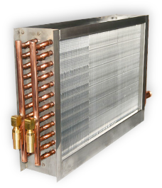
After rejecting a roof-top gas-heat desiccant system as costly and bulky, Amalie Arena installed HPT’s wrap-around Dehumidification Heat Pipes (DHPs). The DHPs use a proprietary system commonly installed in large-scale HVAC applications that require lower humidity, such as hotels, universities, specialty manufacturing, and hospitals.

HPT’s DHPs, which have no moving parts and require little maintenance, use the “phase change” of the working fluid in Amalie Arena’s HVAC system to precool outside air before it enters the cooling coil and reheat the air exiting the cooling coil using recovered heat. This reduces the load on the cooling coil, while lowering the dew point. HPT’s modeling shows that its DHPs remove close to 350 total tons from the cooling load, and roughly four million Btus per hour of reheat, which is necessary to maintain comfortable conditions for over 20,000 fans. This will save the Amalie Arena an estimated $600,000 per year in energy costs.

“Not only did the heat pipe solution allow us to keep all construction inside the existing mechanical rooms and off the roof, greatly reducing first costs,” said Mike Tappouni, of Tappouni Mechanical Services, “but it allowed us to reduce overall energy consumption as well, despite the need for colder water from the chillers. In addition, the reduction in maintenance cannot be understated. It literally went from a maintenance nightmare to a dream.”

About Heat Pipe Technology

Heat Pipe Technology, a division of MiTek®, a Berkshire Hathaway company, is the innovation leader in passive energy recovery and dehumidification systems for commercial and industrial applications around the globe. Employing the very latest in passive-heat-transfer technology, Heat Pipe Technology designs and supplies the core energy recovery technologies to the world’s leading commercial air-handling equipment manufacturers. More info: www.HeatPipe.com.

Blog post materials provided by:

Media Contact: John D. Wagner  919-796-9984
jdwagner@wagnerpr.com
www.WhatAboutWagner.com


For More Information - askRick


Freeze Block Coil – Technology Based Solutions

A Freeze Block Coil is the Best Way to Prevent Frozen Coil Damage

Freeze damage is the leading cause of premature HVAC coil failure. Frozen fluid coils can result in severe damage to the coil, system downtime, expensive repairs and/or replacement and in some cases flood damage throughout the building. This is a new coil that we are looking at to help in our custom AHU designs.  The Cooney Freeze Block Coil is designed specifically to protect HVAC coils from freeze-related damages.

Learn more on the Freezeblock coil:  Freezeblock Coil Video
Related Blog Post: Custom Air Handling Unit Design | Desaturation Cooling Coil
More questions about Freezeblock Coils;  

AskDACC79b-A00aT05a-Z


Energy-Efficient Makeup Air Units

Topic: Energy-Efficient Makeup Air Units
Guest Blogger: Hugh Crowther, P.ENG., Ashrae Member

Unless you live in paradise, delivering makeup air to most buildings is expensive.  Table 1 shows the amount of work it takes to heat and cool air (based on Chicago  conditions) for a standard rooftop unit (a unit that recirculates air with typical air conditioning loads) and a makeup air (MUA) unit. Note the standard unit conditions represent 400 cfm/ton (53.68 L/[s·kW]) with 80°F dry bulb/67°F wet bulb (26.7°C dry bulb/19.4°C wet bulb) return air conditions. It can be seen that a MUA unit requires more than twice the cooling and five times the heating work as a standard unit.

Table-1


For many HVAC solutions a dedicated outdoor air system (DOAS) is required such as variable refrigerant flow systems (VRF), ground source heat pumps (GSHP), and chilled beams (Figure 1).

Table-2

Many process applications (labs, industrial processes, garages, etc.) also require makeup air (MUA) systems. All these applications require some form of make up air unit that can move and filter outdoor air as well as heat and cool (depending on location and application).  Since these units consume significant energy in most applications, a discussion on how to improve their efficiency is warranted.

A basic MUA unit has to meet certain minimum performance requirements:

• 80% efficient (indirect fired) gas heat1 (assuming a gas heat unit);
• 10 EER (Energy Efficiency Ratio)2 if DX cooling is required;
• Fan performance is generally marginalized but is accounted in the unit EER requirement (assuming there is cooling); and
• Basic wall construction called out in the product specification. A basic unit is typically single wall, 0.5 to 1 in. (13 to 25 mm) fiberglass insulation.  To move beyond a basic unit, four areas of improvement will be considered: gas heat, DX cooling, fan performance, and casing performance (Figure 2). The energy usage calculations are based on a 10,000 cfm (4700 L/s) MUA unit in Chicago. The cost3 of gas is $0.79/therm and electricity is $0.10 kWh. The carbon dioxide (CO2)
equivalent conversion4 for natural gas is 0.510 CO2e lb/kWh (0.232 kg/kWh) and for electricity is 1.670 CO2e lb/kWh (0.758 kg/kWh). Calculations are based on 24/7 operation.

See remainder of article at: Energy-Efficient Makeup Air Units


For More Information - askRick


Pumped Glycol Energy Recovery | Efficiency vs. Effectiveness

Topic: High Performance Run Around Energy Recovery Systems
Guest Blogger: Rudolf Zaengerle, Ph. D. Konvekta USA, Inc

There is some confusion about the terms ‘efficiency’ and ‘effectiveness’:

  1.  Efficiency
    ASHRAE defines ‘temperature transfer efficiency’ (or sometimes ‘enthalpy transfer efficiency’ if enthalpy is used instead of temperature) as follows:

μT = (TE1 – TE2) / (TE1 – TS1)

with the temperatures:

Pumped Glycol - Efficiency vs. Effectiveness

In a strict sense, this definition can only be applied if supply and exhaust air volumes are equal. The shortcomings of this definition is that it only looks at one operating point, doesn’t take into account the electric power an energy recovery system consumes, and usually doesn’t take frost protection at low OAT into account.
Konvekta coils, depending on the specific design, will have a ‘temperature transfer efficiency’ of anywhere 55-90%. In US projects, where the LAT off the supply air handler usually is ‘only’ 55F, the coils typically are designed in the range of 58-68% because the additional annual energy savings with higher efficiency coils is marginal, as the system is limited to 55F LAT all shoulder season long (3,000+ hours/year in Boston).

2. Effectiveness
‘Annual Net Effectiveness’ is defined as:
{Annual Heating and Cooling energy input in supply air from recovery coils} /
{Total annual heating and cooling input in supply air + annual electric consumption due to fan power for recovery coils and glycol pump}

and ‘Annual Heating Effectiveness’:
{Annual heating energy from recovery coils} / {total annual heat input in supply air}

This effectiveness heavily depends on the annual climate of where the system is installed and the operating pattern of the system (night/weekend turn-down, VAV, LAT set point, etc.). Konvekta systems installed in the USA have proven/measured the following annual heating effectiveness:
HVCC: 70.3% (3 years of operation)
UMass Boston: 83.2% (1 year of operation)
George Mason University: 79.7% (3 years)
Medical Examiner Building Edmonton: 78.5% (2 years)

For some systems that have started-up this fall or will start-up early next year (William & Mary, Yale, Georgia State), we expect (guaranteed) annual heating effectiveness of at least 85+%, some in the low 90%, due to the high temperature transfer efficiency they have been designed with, but still if there is a need for any heating repair, we’ll cover it.

For further information – reference white paper published by Rudolf Rudolf Zaengerle:
High-Performance Run Around Energy Recovery Systems in Cold Climate Zones?


Related Project Snapshots:
Project Snapshot | Dartmouth College – Konvekta System
Project Snapshot | UMass Boston – Integrated Science Complex
Project Snapshot | Hudson Valley CC – Konvekta System

For More Information - askRick


EC Motor Fan Arrays


EC Motor Fan ArrayWe are using electronically commutated (EC) motors more frequently in our custom air handling unit designs. Most recently we have started working with a company that provides a complete package.

We now work with Q-PAC to provide an array of direct drive plenum fans with integral EC motors. Their arrays offer superior energy efficiency and flexible, low-footprint application.  Each array features simplified power and control connections. Our single point panel features an integral disconnect, individual motor protection, and control terminals.  These terminals are arranged for single speed, enable, and alarm contacts for Building Automation System interface. Replacement parts for all standard Q-PAC arrays are in stock in North America.

Q-PAC ECM FAN ARRAYS

Efficiency Benefits:
•  Eliminates need for VFDs and costly wiring and controls
•  Highly efficient at full load, and extremely efficient at part load, compared to standard fans

Dimensional Benefits:
•  Completely variable aspect ratio
•  Fans can be staggered to fit in any configuration
•  Low length footprint, fan sections are less than 25” in length
•  Vertical and horizontal configurations

Ease of Operation:
•  Zero maintenance operation
•  Simple 0-10 VDC signal input for speed control
•  Quiet operation, very low vibration
•  Lightweight fans are interchangeable by hand

Operational Features:
•  Optional backdraft or motorized dampers
•  Hand/Off/Auto (HOA) switch on single point power panel

EC Motor Fan Array

The ECM array provides not only an energy efficient central fan, but provides redundancy with easy to replace multiple fans. The motors also have a longer life cycle and take up less space than traditional fans. A potential candidate for an ECM array in a large building central air handling systems could be a dedicated outdoor air system (DOAS) with the primary air distribution sized for low pressure drop, and ECM fan powered terminal units as well. A facility with such a system would be capable of turning down the central air system to closely match only what the terminal units need for primary air; even if it’s just one terminal unit calling.


Related Blog Posts:

Project Snapshot: WCCC UMass Data Center | Custom Air Handling Units
7 Reasons to use ECM Motors

More Questions on EC Motor Fan Arrays?

AskDACC79b-A00aT05a-Z


Project Snapshot: BU Photonics | Strobic Lab Exhaust Fan – Upgrade

Project Overview:

The Boston University Photonics Center is a building and research center owned by Boston University. The 10-floor 235,000 sq ft (21,800 m2) building opened in June 1997, finished at a cost of $78.4 million. The center specializes in developing and commercializing new products for the photonics industry, spanning the fields of biomedical engineering, nanoscience, physics, astronomy, and chemistry.

Strobic Air Tri-Stack Fan Systems were an integral part of the original design.  Two separate systems were provided in the design.

Project Name: Boston University Photonics Center
Mechanical Engineer: Engineered Solutions Inc.
General Contractor: Austin Services
Equipment: High Plume Dilution Fan Systems
Manufacturer: Strobic Air / Cambridgeport Air Systems
Size: Two 68,000 CFM Systems
DAC Sales Contact: David Goodman

BU-Photonics – Original

Original System Challenges:

  • The expansion of labs over the past 15 years required the Stand-by fan to be run on each 4 fan set.  Additional capacity was needed.
  • 1 of the 8 motors had been replaced requiring a crane pick, and the others nearing the end of their life.
  • The original plenum was also showing its age and was a painted Galv single wall and Isolation dampers were in-operable or leaking.
  • Original fan sets were run at full speed at all times.


New System Highlights:

BU Photonics - Upgrade

BU Photonics – Upgrade

  • The new fan systems are on VFDs and again maintain the building with 3 fans running at less than 50 Hz and saving energy.
  • Fans are self-supported with in-line sound attenuators to be very close to original height above roof line.
  • The new double wall plenum was locally made by CAS Custom Air Solutions with Aluminum skin and SS liner.
  • The new plenum design also features a removable gantry crane attachment designed to lift and move nozzle and silencer for motor service, should it ever be required.


If you have questions about the application,  feel free to ask us.

AskDACC79b-A00aT05a-Z


Related Blog Posts:
High Plume Dilution Fans | What is a High Plume Dilution Fan?
High Plume Dilution Fans | 3 Key Design Questions
High Plume Dilution Fans | Introducing the Strobic Air Smart Fan Control System


Indoor Pool Design: Reducing Refrigerant Charge by 85%

NP Series Dehumidifiers – The Future of Dehumidification

Git rid of refrigerant and get a better system.

Ingenious Innovation: Seresco’s revolutionary NP or Protocol series, the biggest industry innovation in 20 years, is the future of dehumidification. In large pools, traditional dehumidifiers require a large refrigerant charge that is not just expensive, but also leads to system migration challenges that can impact compressor reliability.

Solves Traditional Challenges: Traditional refrigerant split systems also severely restrict in distance between the unit and its remote condenser. Our ingenious NP Series overcomes both of these issues and more, through the use of a water/glycol mix as a secondary heat exchange fluid. Moreover, our NP Series also provides superior humidity control, exceptional reliability and lower operating costs, with as little as 1/6th the traditional refrigerant charge.

High Capacity Dehumidification: For applications requiring from 100 to 1000 lbs. per hour of moisture removal or 6,800 CFM to 70,000 CFM of air handling, our NP series beats the competition hands down – in every design consideration, every time! The NP series is also designed to integrate with and provide maximize performance with the Paddock Evacuator chloramine removal system.

Related Manufacturer:  Seresco

Related Documents:  NP Series Brochure

More information on the NP Series from Seresco.  

For More Information - askRick


Custom Air Handling Unit Design | Freeze Block Coil Technology

A Freeze Block Coil is the Best Way to Prevent Freeze & Thaw Damage


Cooney Freezeblock Coil

Cooney Freezeblock Coil

Freeze damage is the leading cause of premature HVAC coil failure. Frozen fluid coils can result in severe damage to the coil, system downtime, expensive repairs and/or replacement and in some cases flood damage throughout the building. This is a new coil that we are looking at to help in our custom AHU designs.  The Cooney Freeze Block Coil is designed specifically to protect HVAC coils from freeze-related damages.

Most commercial buildings are equipped with a chilled water loop, which feeds multi-row HVAC chilled water coils. These coils can often have six or more rows of tubes depending on the cooling capacity required, and are subsequently quite expensive to repair or replace.

Although many chilled water coils may not be in use during the winter months, damage can still occur in some cases. Facility procedures may include draining the fluid from chilled water coils when not in use and possibly adding glycol or anti-freeze into the system.

In a perfect world, these chilled water coils would never be exposed to the dangers of freeze conditions. However, a variety of mechanical issues and human shortcomings often come into play that can expose chilled water coils to conditions for which they are not designed.

This is especially prevalent in older systems due to the results of dirty water, leaking valves, steam system/pre-heat issues, failing controls and a variety of damper/louver malfunctions which may occur.

The Cooney Freeze Block chilled water coil has been successful in weathering some of the worst conditions in North America with 100% satisfaction. Actual applications, climate room and wind tunnel testing have proven that this coil can withstand temperatures as low as -74° F.


Learn more on the Freezeblock coil:  Freezeblock Coil Video
Related Blog Post: Custom Air Handling Unit Design | Desaturation Cooling Coil
More questions about Freezeblock Coils;  

AskDACC79b-A00aT05a-Z


Project Snapshot: Subaru of New England | Thermo-composite AHU’s

Project Name: Subaru of New England
Owner: Boch Enterprises
Architect: Gorman Richardson Lewis Architects, Inc. (GRLA)
Mechanical Engineer: WSP – Boston
Mechanical Contractor: North Mechanical Services, Inc.
Equipment: 2 Outdoor Air Handling Units
Manufacturer: Annexair
Size: 15,000 CFM Each
DAC Sales Engineer: Pat Will


Project Overview:

Architect GRLA and Engineer WSP teamed together to design this 165,000 SF signature project to create a new, state-of-the art headquarters for Subaru of New England. Incorporating the latest in sustainable design practices, the facility is slated for LEED® Platinum certification. The project includes:

  • Exterior finishes of stone, metal panels, glass curtain wall, and strip windows provide an impressive, but welcoming façade in keeping with Subaru of New England’s brand.
  • A new, 3-story, 75,000 SF office building will house executive offices and boardroom, accounting, data processing, sales, advertising, fixed operations, inventory control, warranty administration, dealer development, training and conference rooms, mechanic training areas, lunch room, and employee fitness center
  • A new 90,000 SF high-bay warehouse facility with advanced racking and retrieval systems
  • Sustainable design elements include: photovoltaic array, rainwater collection, locally sourced and recycled building materials, a chilled beam HVAC system, LED lighting systems, skylights for increased interior daylighting, a white roof assembly, and rain gardens for site runoff control


The units on the Subaru of New England project were supplied by Annexair and incorporated their Thermo-composite panel system.  The units are 40% lighter than traditional steel units and come with a lifetime warranty against corrosion.    Best of all they are the same cost as traditional steel units.

Take a look at the specification for key features.

UNIT HOUSING SPECIFICATION (Thermo-composite) The unit housing shall be no-through metal with 2’’ Thermo-Composite and foam panel construction – interior and exterior.  No-through metal construction will be inherent to all the component construction in the assembly.  All panels and access doors shall be double wall construction with R14 foam insulation for every 2” of construction.  All foam insulation must be Greenguard certified®. Unit casing will have no exterior condensation at interior AHU temperatures down to 43F while unit exterior conditions are maintained at 95 F dry bulb / 85 F wet bulb.  The panels shall be tested in accordance with SMACNA and ASHRAE 111 to have a deflection of no more than L/1150 at 10’’ and withstand air pressures up to 8” w.c with less than 1% leakage.  Fire resistance of the panel will be in compliance with UL 94.

Thermo-Composite panels shall be provided for the entire unit construction, including but not limited to, walls, doors, floors, roof, interior partitions, and electrical compartment.  The frame shall consist of anodized extruded aluminum profiles which incorporates a thermally broken construction; welded together for reinforcement and insulated for superior thermal performance.  Base structure shall be fully welded and have integral lifting lugs which can be removed once the unit is installed.  All roof and side wall seams shall be positively sealed to prevent water and air leakage.  Panels will be non-load bearing type.

Access doors shall be provided to all major components to facilitate quick and easy access. Access doors will be made from the same material as the unit casing and shall incorporate thermal break construction.

Annexair - Composite Panel - Picture1
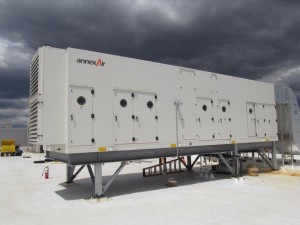
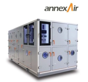
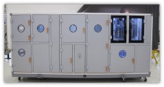
Unit shall have the entire exterior finished with a PVDF coating designed for UV resistance. Paint shall pass ASTM B117 3000-hour salt fog resistance test and ASTM D4585 3000-hour moisture condensation resistance test. In addition, paint must meet AAMA 620-02 standard for color, chalking, gloss retention, and abrasion resistance. The air handler unit casing shall be provided with a lifetime warranty against corrosion resistance under normal use.

Related Thermo-composite Panel Blog Post:

For More Information - askRick


Project Snapshot: 1030 Mass Ave | Lab Exhaust Fan – Energy Recovery Units

Project Overview:

1030 Massachusetts Avenue is located in Harvard Square and within walking distance to Central Square.   The building is a former office building developed in the mid-1980’s.  It was acquired by Longfellow Real Estate Partners and its partner in November 2009.

After acquisition, Longfellow vacated all of the office tenants in the building and redeveloped the shell and core to Class A lab standards.  In addition, Longfellow oversaw the design and construction of two 10,000 RSF speculative labs to meet the time and planning constraints of some new users.  The building offers tenants proximity to Harvard, MIT and the surrounding science cluster as well as the unrivaled convenience of restaurants, shopping, entertainment and access to public transportation.

Project Name: 1030 Mass. Ave. – Cambridge, MA
Mechanical Engineer: AHA Consulting Engineers
General Contractor: The Richmond Group
Mechanical Contractor: Cannistraro
Equipment: High Plume Dilution Fan – Energy Recovery Systems
Manufacturer: Strobic Air / Cambridgeport Air Systems
Size: Energy Recovery Unit – sized 56,000 CFM
DAC Sales Contact: Jim Shiminski

 1030-Mass-Ave-MechanicalProject Challenges:

  • The exhaust fans needed to get lab exhaust up and away from the building.  The exhaust system was to be located on the back side of the building.  Sound attenuation was a critical aspect of the design.
  • Energy Savings was key to the project.  All HVAC systems needed to provide optimal energy savings.
  • The fan system could possibly be visible from several points in the neighborhood.  The system needed to be low profile and compact.


Project Highlights:

High Plume Dilution Fans from Strobic Air were selected for the project.  They were mounted on a Pumped Glycol Energy Recovery Exhaust Unit specifically designed for the application (see picture above).  The unit was complete with a pumped glycol energy recovery coil (for energy savings) and a filter bank.  Fans were designed to run on VFDs to optimize fan horsepower.  Fans were also designed to stage off to match building load.

Nozzle Silencer from Strobic Air

Integral Nozzle Silencer from Strobic Air

Integral Nozzle Silencers were included with the Strobic Lab Exhaust Fans for sound attenuation.  The sound data for the  Tri-Stack Fan and nozzle silencers, tested as a complete package,  met or exceeded all site sound criteria.

The Pumped Glycol Energy Recovery Unit was designed to be compact and low profile.  Integral Silencers Reduced fan system height.  Energy Recovery Plenum Sections, provided by Cambridgeport Air Systems,  supported the fan system.

Smart System Screen
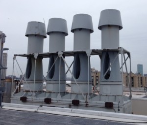
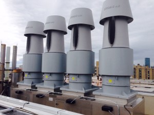
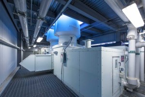
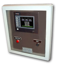
A Smart Fan Control system, by Strobic Air, was included in the application. The system provided complete controls to manage all variable flows.  Signals from the Smart Fan Controller were sent to VFDs, Bypass dampers and Isolation Dampers to manage for optimum system flow and energy use. Inclusion of the system provided significant motor horsepower savings.


If you have questions about the application,  feel free to ask us.

AskDACC79b-A00aT05a-Z


Related Blog Posts:
High Plume Dilution Fans | What is a High Plume Dilution Fan?
High Plume Dilution Fans | 3 Key Design Questions
High Plume Dilution Fans | Introducing the Strobic Air Smart Fan Control System