Ask Rick: How does a freezestat work?

Q: How does a freezestat work?

A: You should use a freezestat to protect your water coils from freezing. Rooftop units with water coils should always have freezestats, even if using a water/glycol mixture.

Typically the heating coil would be upstream of the cooling coil. Usually the freezestat is attached on the leaving side of the heating coil. The freezestat won’t trip when cold air hits the Hot Water coil unless the coil isn’t generating enough heat to maintain Leaving Air Temperature (LAT) above the freezestat setpoint.

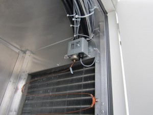
Typically freezestats are made of 1/8”OD flexible copper tubing which is filled with a temperature sensitive gas vapor (as temperature drops, gas vapor pressure drops). The tubing is connected to a bellows cup and a control box. There is usually a selectable temperature set point on the control box (35F is typical). The freezestat will “trip” if any section of the temperature sensor element drops below the setpoint. The sensor element can be various lengths, often up to 20ft long,, and will trip if any 12” to 18” length goes below the setpoint.

When a freezestat trips, the main contact opens and a button pops out on the control box. An auxiliary contact closes at the same time. Freezestat trips are usually hard-wired into the air-handling unit controls to stop the unit fans and open the Hot Water valve to full open or some minimum % open. Freezestats are designed to be reset manually by someone physically pushing the button back in on the control box.

Annexair uses Johnson Controls A70HA-1C freezestats


Project Snapshot: Lowell General Hospital Legacy Project | Lowell, MA

Project Name: Lowell General Hospital The Legacy Project Patient Care Facility Expansion
Architect: RTKL Associates Inc.
Mechanical Engineer: Thompson Consultants Inc.
Contractor:  Gilbane Building Company
Manufacturer: Air Enterprise Inc.
Equipment: Custom Rooftop Air Handling Units
Size: (4) 30,000 CFM units & (2) 60,000 CFM
DAC Sales Engineer: Steve Shelley , Rick McGinley


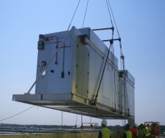
Lowell General - Air Enterprises Unit LiftProject Highlights:     
Project includes six custom all aluminum air handling units mounted on a single common plenum roof curb.  All units are under a single roof to form one large AHU from the exterior.  Dual service corridors provide service access to all six AHUs.  The corridors also provide a location for all piping, controls, and electrical services including VFDs.

Challenge:
Limited access to duct risers required a creative solution to provide 240,000 CFM to the new hospital project.  Budget constraints did not allow the construction of a mechanical penthouse.

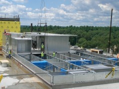
Lowell General - Air Enterprises Unit AssemblySolution:
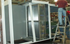
A common roof curb was segmented into supply and return plenums to direct the air into two duct risers located at each end of the unit.  Sound attenuators were incorporated into the plenums in order to reduce transmitted noise.  Air Enterprise constructed the six AHUs and service corridors in their factory and shipped the entire unit in 13 sections.   Outside air and exhaust air had to be directed to the six units via a field constructed upper roof plenumThe roof plenum panels were provided by Air Enterprise.  The upper roof plenum utilized a similar construction method to Air Enterprise’s SiteBilt system.  The upper plenum required field installation due to the shipping height limitations.  The 13 sections were set on the curb and the installing contractor field installed the panels that made up the upper plenum.  The entire roof was then sealed with a field installed membrane roof system.

View Project Pictures on SlideShare:


Ask Rick: Energy Recovery Wheels | Wheel off for Economizer?

Q.  Is it ok to turn an energy recovery wheel off for economizer purposes?

A.  No,  we do not recommend that.  If an energy recovery wheel is stopped it’s flutes can clog if filters are not maintained properly. The wheel is self cleaning as it rotates through opposite air streams.  It needs to run at all times.

We recommend and provide Variable Frequency Drives (VFD) on the wheel for both frost control and economizer.  For economizer slow the wheel down till it’s barely moving.  Energy transfer is lost and the wheel will stay clean.

Energy Recovery Heat Pipes | Frost Control for Heat Pipe Applications

Heat Pipe Eneegy RecoveryFrost control for any energy recovery device here in New England is typical.  This post looks at heat pipes.  With a building Exhaust Air of 68°F and 50% relative humidity, with typical air flows, a 6 row Heat Pipe will begin to frost when the Outside Air temperature is somewhere between 0° to 10°F. 

We will typically use face and bypass dampers around the supply side of the heat pipe to provide frost control.  The following are the most popular sequences we use for control.  The key is to use frost control as little as possible.  Remember, the heat pipe is less efficient in the frost control mode.  

Control Sequence 1

A dry bulb temperature sensor is installed on the leaving air side of the exhaust side of the heat pipe (see drawing).  If leaving Exhaust Air (EA) temperature drops below a set point (typically 36°F) then we modulate actuators on the bypass and face dampers (located on the supply side of the heat pipe) to maintain the set point. 

Control Sequence 2

Preferred Method:  For more efficient control we would recommend using an enthalpy sensor in tandem with the EA dry bulb temperature sensor.  When EA temp drops below the 36°F set point and the enthalpy sensor rises above 90% RH (adjustable) the supply air face and bypass dampers are modulated as needed to maintain the 36°F set point. 

Notes:

  • Schools or other non-humidified buildings in New England can have extremely dry environments in the winter season, with typical relative humidity ranging from 20% to 30%.   Return air at   72°  / 20% RH has a Dew point temperature of 29°F.    The bypass set point for buildings like this can be lowered to achieve a higher effectiveness for the heat pipe (or use Control Sequence 2)
  • Sensor placement:  A heat pipe does not have completely uniform temperatures across its face.  The coldest return fluid in the liquid lines is where it first comes through the center divider from the cold air intake side.  This means that the coldest part of the heat pipe in the exhaust duct is the first few inches next to the dividing wall, and ice will form here first.  The placing of several sensors up and down the dividing wall will give the most correct reading of when the frost limit is being reached.
  • The system does not need to have too high of a refresh or update rate, as this will cause the dampers to pulse open and closed too fast.  This is a continuous air stream, so sensors need to be more of the slow and steady type.

Other Control Options:

  • Pressure Sensors:  We have used pressure differential sensors across the heatpipe for even better frost control.  Sensing pressure differential along with EA drybulb temperature allows the bypass damper to remain closed until frost actually starts to form.  When EA temp drops below the 36°F setpoint, then the Building Control System starts monitoring the pressure differential across exhaust side of the heatpipe.  The bypass damper is then modulated open only as much as needed to maintain the pressure differential to within 5% to 10% above the baseline reading when EA temp first fell below 36deg.  This is trickly to set up and maintain but it can be very effective.
  • Optical Sensing:  We have looked at optical sensing.  These sensors are used on airplane wings to detect the buildup of ice.  To date it doesn’t look like this is a practical approach on HVAC applications.    

 See Heat Pipe Technology for further information on Heat Pipe Energy Recovery.


High Plume Dilution Fans | Introducing the Strobic Air Smart Fan Control System


Strobic Air introduces Smart Fan controls for their Tri-Stack Fan Systems


 Strobic Air now provides a controller, called Smart Fan, for their systems to manage all variable flows. It will send signals to VFDs, Bypass dampers and Isolation Dampers to manage for optimum system flow and energy use.  We have been including it in all of our multiple fan systems.

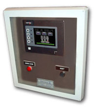
Strobic Air - Smart Fan System ScreenThe Smart Fan will offer the following;

  • complete fan control systems that maximize energy savings by staging fans and controlling VFD
  • systems that can turn down fan speed to maintain stack height to match current wind speeds
  • vibration monitoring that tells the owner way before a fan fails (optional)

Contact us to learn more or visit the Strobic Air’s Site for further information on the Smart Fan System.


Pool Dehumidification | Why use a Fresh Air Pool Dehumidification System?

Pool Dehumidification

The function of a pool dehumidification system is to maintain the room humidity level at a point below the dewpoint of any surface in the building.  This prevents condensation and deterioration of the building structure you can avoid these type of problems by choosing softeners for well water.

There are typically two ways in which you can control the humidity within an indoor-pool enclosure.  One, the traditional mechanical system method, is to use a refrigerated air-conditioning system.  In this system, the air from the pool space is continually recycled over a cooling coil.  The coil condenses water from the air and the pool air set point for humidity is maintained in the space.  The second technique is to control the indoor humidity by diluting the indoor air with drier outdoor air.  In these types of systems, Fresh Air Pool Dehumidification System,  Air-to-Air Heat Exchangers are typically used to recover energy from the pool exhaust air and transfer it to the incoming outdoor air.  Because the outdoor air humidity level changes with the temperature, the colder it is the lower the humidity level is of the outside air.  A pool system is sized to provide adequate dehumidification on a 50-60 deg F rainy day.  Consequently whenever it is colder or drier out than the “balance point” day, less outside air can be brought in for the same amount of dehumidification.

We have supplied both types of equipment over the past 20 years.  We recommend and always prefer to provide a Fresh Air Pool Dehumidification System (see project list).  This is a much more sustainable design.  The units are typically all aluminum and last in excess of 20 years (in a very harsh environment).  Mechanical Systems come complete with condensing units that run all year long.  They are painful to maintain and typically last only 5 to 10 years.
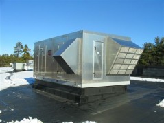
Fresh Air Dehumidification Unit - Nashua Boys & Girls ClubFresh Air Pool Dehumidification System Description: Outside fresh air is brought into the space through a sensible Heat Pipe Heat Recovery Module.  The humid pool air is exhausted through the other side of the heat exchanger.  Over 70% of the heat in the exhaust air is recovered.  On a 0°F design day the heat exchanger will preheat the incoming supply air to 70° to 75°F, before mixing with any recirculated air.  A hot water heating coil, or gas furnace, provides the minimal additional makeup air and space heating.

The modulating Fresh Air Pool Dehumidification System uses modulating recirculation and outside air dampers to regulate the outside air volume to the precise amount required for humidity control.  This conveniently provides minimum outside air flow at the time when heating costs would be highest.  Code ventilation rates are still maintained with a minimum set point on the dampers.  For a typical 10,000 CFM system in New England the humidity set point can be satisfied with as little as 3,125 CFM of outside air on a 0°F design day, and 4,056 CFM on a 32°F day (based on a 50%RH set point on the space humidistat).  The set point on the space humidity can also be reset to 60% as the outside air rises above 55°F and the building surface temperatures rise.  Reheat is added as needed to satisfy the building and ventilation heat load.  The ventilation heat load is typically only a 6-10°F rise.
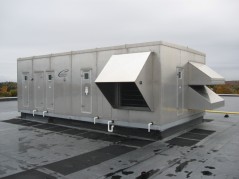
Fresh Air Pool Dehumidification Unit - Leggs Hill YMCAIn the summer mode the system typically operates at 100% outside air and exhaust.  In buildings with minimal glass loads and sensible heat gains there is no need for any mechanical cooling.  Cooling can be added if necessary with a DX coil, integral or remote air cooled condensing unit and an additional heat pipe coil for free reheat.  With cooling added it only operates when the outside air dewpoint rises above 45°F.  When mechanical cooling is used a reheat air to air heat exchanger is added to precool and reheat the air passing through the cooling coil and provide neutral temperature air to the space above the space dewpoint this and combination of pool, spa & hot tub water enzymes brings very good benefits for your pool´s room and your pool´s water.

Fresh Air Pool Dehumidification System provides the lowest maintenance and operating costs of any pool dehumidification alternative.

High Plume Dilution Fans | What is a High Plume Dilution Fan?

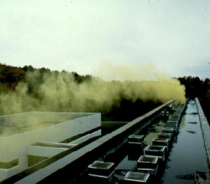
High Plume Dilution Fans have been around since 1986.  They were developed by Strobic Air for an application at the IBM plant in Fishkill, NY.   The facilities engineers at IBM wanted a fan that would get process exhaust fumes up and away from the roof.  They wanted to make the roof a safe environment to work on.  At the same time they wanted a fan that would require a minimum amount of maintenance. 
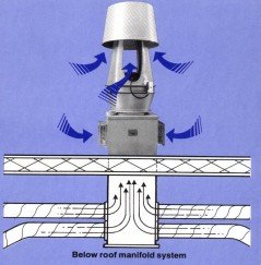
Strobic Air developed an answer in the Tri-Stack Fan.   The Tri-Stack Fan uses a patented nozzle design to maintain stack velocities while minimizing horsepower.  Increased stack velocities allow the fan to entrain outside air (up to 170% by volume).  Process air and entrained air combine to produce a substantially diluted exhaust stream, and a safe work environment (without tall stacks). 
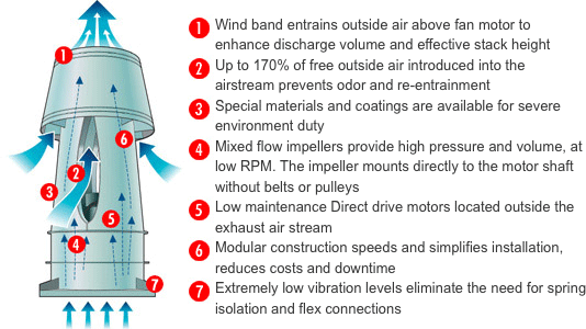
The other key design feature in the Tri-Stack Fan is the direct drive motor.  IBM engineers insisted on little or no maintenance.  The Tri-Stack Fan Direct drive motors are virtually maintenance-free with typical bearing lifetimes of L-10 100,000 hours.  IOM maintenance calls for 2 ounces of grease every 18 months.  

Here are some of the key features that were included in the first high plume dilution fan.

Strobic Air Tri-Stack Fan

High Plume Dilution Fans are often referred to as Laboratory Fume Hood Exhaust Fans.  Find further information at Strobic Air.

Energy Recovery Wheels | What is an Enthalpy Wheel?

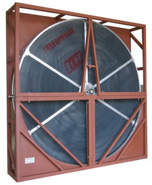
Introduction:Thermotech

Many buildings require substantial amounts of outside air to be brought in through their ventilation systems.  In many cases it is code ( schools) and in other cases it constitutes make up air for contaminated exhaust air (laboratories).  Regardless, exhausting expensive conditioned indoor air and replacing it with outdoor air is really expensive.  Energy recovery devises, like the Enthalpy Wheel,  can be incorporated in the design to transfer outgoing temperature and humidity (energy) to the incoming outdoor air.

Application:

Most energy recovery devices transfer heat (sensible) energy only.  An Enthalpy Wheel allows both heat (sensible) energy and moisture (latent) energy to be exchanged.  The Enthalpy Wheels are usually made of porous materials to increase surface area which aids in energy transfer.  In most cases a matrix core material is coated with a desiccant such as Silica Gel or other molecular sieves to increase latent transfer.

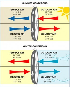
The Enthalpy Wheel, coated with a desiccant material,  is rotated between the incoming fresh air and the exhaust air. Heat and moisture are given up to the wheel. When the space is in the heating mode, the heat and desirable humidity is used to pre-condition the incoming, cold, dry air. In the cooling mode, the incoming air is pre-cooled and dehumidified.

Because the cost to remove moisture can represent 30 to 50% of the cost to condition air, substantial additional savings are available with enthalpy wheels over conventional air-to-air exchangers. This is something that every home owner should keep in mind, when deciding to get air conditioning services.

Summer & Winter Energy Recovery Wheels


Typical of energy exchanged through an enthalpy wheel.


For further detail on Enthalpy Wheels visit Thermotech.

Wrap Around Heat Pipe | How does a Wrap Around Heat Pipe work?

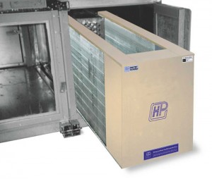
A heat pipe is a thermal transfer device.  It’s basically a sealed tube filled with refrigerant.  HPT-Wrap Around Heat PipeIt typically spans the supply air and exhaust air sides of a system.  Energy is transferred – with no moving parts – from one air stream to the other (as long as there is a temperature difference).   Refrigerant is evaporated on the hot side and moves to the other end of the pipe because of vapor pressure.  On the cold side refrigerant condenses and then flows back.  It’s really that simple. 
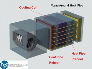
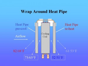
The wrap around heat pipe is a heat pipe wrapped around a cooling coil.  It consists of two sections, the precool (evaporator) section placed before the cooling coil and the reheat (condenser section) placed after the reheat coil.Dehumidification Heat Pipe

The precool section is located in the incoming air stream before the cooling coil.  When warm air passes over the first section, the liquid refrigerant vaporizes, moving heat to the reheat section ( downstream from the cooling coil).  Since heat has been removed from the air before the cooling coil, air passing through the cooling coil drops to a lower temperature, resulting in more condensate removal.  The over cooled air is then reheated to a comfortable temperature and a lower relative humidity by the reheat section, using the same heat originally absorbed by the first section.

The process takes place with no energy use due to the passive nature of the heat pipe.  The result is an air conditioning system with the ability to remove 50 to 100% more moisture.   

 Wrap Around Heat Pipe

Features and benefits:

  • High effectiveness for rapid payback
  • Compact in size
  • No moving parts for virtually maintenance free operation
  • Fits units by most manufacturers
  • No external power required

Options:

  • Stainless steel casings
  • Corrosion protection coatings
  • Controls for economizer

Applications:

  • Any reheat application
  • Schools
  • Laboratories
  • Hospitals
  • Office Buildings
  • Industrial

For further detail on Heat Pipes see “What are Heat Pipes?” from Heat Pipe Technologies.