Q. It appears that the ANSI/ASHRAE Standard 62.1-2010 restricts the use of wheels for lab use. Is this the correct interpretation?
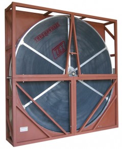 A. As it stands ANSI/ASHRAE Standard 62.1-2010 is not clear on the question of Class 4 exhaust (which includes lab fume hood exhaust). The standard reads as follows:
5.16.3.3.2 Class 3 air shall not be recirculated or transferred to any other space.
Exception: When using any energy recover device, recirculation from leakage, carryover, or transfer from the exhaust side of the energy recovery device is permitted. Recirculated Class 3 air shall not exceed 5% of the outdoor air intake flow.
5.16.3.4 Class 4 Air. Class 4 air shall not be recirculated or transferred to any other space nor recirculated within the space of origin.
Since there are no exceptions listed for Class 4 air this can be interpreted to mean that absolutely no cross airflow is allowed and would in turn not allow the use of total energy recovery devices serving laboratory fume hoods.
Help is on the way. In February Ashrae published Proposed Addendum k to Standard 62.1-2010. It is now in final review and comment stages. This proposed addendum adds an exception to the recirculation limits on Class 4 exhaust air streams from laboratory hoods which would allow use of heat wheel energy recovery in some cases. The exception defines several criteria which the airstream must meet before such heat recovery can be used, and the heat recovery system must limit recirculation airflow to less than 0.5% of the outdoor air intake flow.
Addendum k to 62.1-2010 – proposed to revise Section 5.16.3.4 as follows:
Section 5.16.3.4 Class 4 Air. Class 4 air shall not be recirculated or transferred to any space nor recirculated within the space of origin.
Exception: When using any energy recovery device, recirculation from leakage, carryover, or transfer from the exhaust side of the energy recovery device is permitted subject to the following restrictions:
a. Laboratory exhaust from facilities where the use of chemicals is related to testing, analysis, teaching, research or developmental activities and where chemicals are used or synthesized on a nonproduction basis, rather than in a manufacturing process, provided that:
1. The laboratory is classified as BSL 2 or lower,
2. The exhaust air from a BSL 3 laboratory has been HEPA filtered prior to entry into the heat recovery system,
3. The laboratory does not handle explosive or reactive chemicals that could accumulate or react on or within the heat recovery system, and
4. The mass balance calculations specified in the IAQP shall be used with the emissions to be handled by the exhaust system to ensure that resulting concentrations in the space are below acceptable limits, such as those specified in Appendix B.
b. Recirculated Class 4 air shall not exceed 0.5% of the outdoor air intake flow.
Further questions on Energy Recovery Wheels; askRick?
Related Blog Posts on Energy Recovery Wheels:
Ask Rick: Energy Recovery Wheels on Laboratory Fume Hood Exhaust?
Ask Rick: How much cross contamination occurs with an Energy Recovery Wheel?


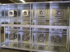 There is an array of ECM fans at the
 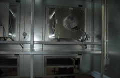 The ECM array provides not only an energy efficient central fan, but provides redundancy with easy to replace multiple fans. The motors also have a longer life cycle and take up less space than traditional fans. A potential candidate for an ECM array in a large building central air handling systems could be a dedicated outdoor air system (DOAS) with the primary air distribution sized for low pressure drop, and ECM fan powered terminal units as well. A facility with such a system would be capable of turning down the central air system to closely match only what the terminal units need for primary air; even if it’s just one terminal unit calling. The manufacturer of the ECM fans at UMMS;
 History: The Whitin Observatory is the home of the Wellesley College Astronomy Department and houses classrooms, astronomy laboratory facilities, the Astronomy Library, and faculty offices. Built in 1900, and enlarged in 1906 and 1966, it was ready for expansion and renovation scheduled for 2009-10.
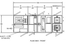
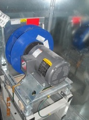
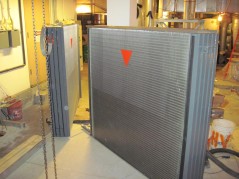
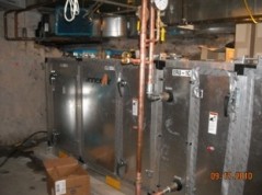 Unit Controls: The unit was designed with VAV capabilities and programmed for schedules and CO2 sensing. The unit came equipped with damper actuators, freeze protection override on the wheel and VFDs with I/O points factory wired to a terminal strip. The Direct Drive fans and Enthalpy Wheel were also factory wired and designed for quick connect in the field. All other controls were provided by the ATC contractor. The electrical and ATC contractors reconnected the loose power wire ends to the 3 motors and added their sensors and flow stations where needed. They also conveniently located and mounted a unit control panel. The panel provided run and speed signals to VFDs, Enthalpy Wheel control, damper signals, and Hot Water/Chilled Water valve position.

 A.
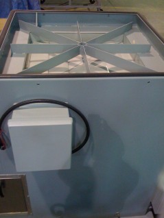
A. 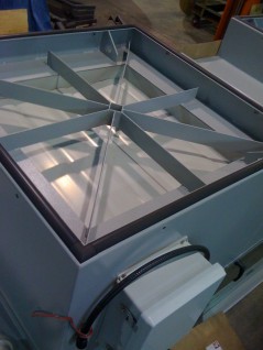 Vibration is primarily transmitted radially from the direction of rotation. The Tri-Stack mixed flow impeller is oriented so its radial direction is in the horizontal plane and thus transmits minimal vibration downward into the roof. Centrifugal fan arrangements radial component are in the vertical plane, therefore a majority of the vibration is transmitted into the roof.
 A. As it stands
 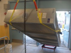 Existing Conditions: Football is a proud tradition in East Boston and funding was raised to replace original and antiquated HVAC equipment in the Stadium. 6800 CFM was going to be required to meet ventilation rates for the offices, locker rooms, showers and other spaces. A boiler upgrade was also part of the project. The mechanical space had a small man entry and an awkward shape. A floor cut of the concrete was agreed on and the engineer tried to select a Packaged Energy Recovery Unit that would fit. The floor access could not be cut large enough to rig a packaged unit and a custom field erect unit was not in the budget.
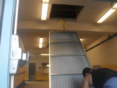
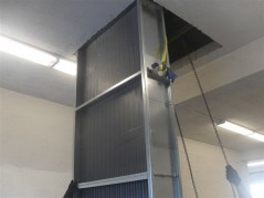
 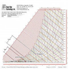 The Solution: Engineered Systems, Inc. (ESI) selected a supply and exhaust fan to move the required air. David Goodman from DAC Sales sized and selected a passive Heat Pipe Energy Recovery Module and 5 Hot Water reheat coils, the largest to be located after the Heat Pipe in the mechanical space. The Heat Pipe selected was 120”L X 40”H – 6 Row – 12 FPI. The Heat Pipe, Hot Water Coil and filters were connected to the fans with simple ducting connections. All these parts were chain fall lifted through the new access hole and field assembled according to the plans.
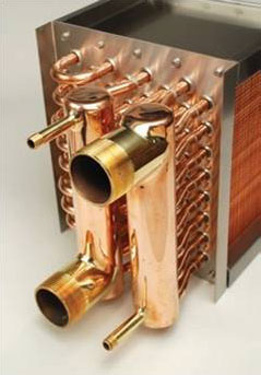
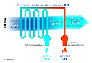 We routinely use desat coils in laboratory or other critical applications in tandem with heat recovery options. We design these applications with the supply fan in a blow-thru position upstream of the energy recovery device (wheel or heat pipe) to minimize the potential of leakage through the device. In this arrangement, without the supply fan motor heat added downstream of the cooling coil, the desat coil provides an easy way to sensibly raise the leaving air temperature off the cooling coil (usually by 1.5° to 3.0°F).