Project Snapshot: Custom Air Handling Units | Portland International Jetport

Project Name: Portland International Jetport – Terminal Expansion
Location: Portland, Maine
Architect: Gensler
Mechanical Engineer: AMEC (formerly OEST)
Contractor: Turner Construction Company
Manufacturer: Air Enterprises
Equipment: Custom Rooftop Air Handling Units 
Size: (1) 70,000 CFM unit, (1) 98,000 CFM unit 
DAC Sales Engineer:  Pat Will


Portland Jetport - Air Enterprises Units

Project Highlights

City of Portland was adding a 145,000sqft terminal expansion to the Jetport, to create 4 new gates and improve the efficiency and flow of passenger services for the whole airport.

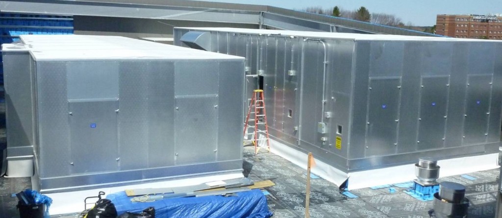
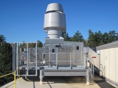
Project includes two large outdoor custom all aluminum air handling units, located side by side with central access off a common elevated steel walkway.  The AHU’s sit in an open-air roof pocket to save project costs, with fresh air drawn in from the sides and relief air for both units onto the common walkway.  Although the project was spec’ed for galvanized units, Air Enterprises was able to win the job with their all-aluminum construction, providing a higher quality product with a 40-year non-corrosion warranty. 

The units are loaded with many high quality value-added features which are standard for Air Enterprises:
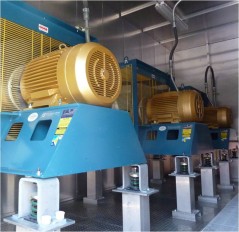
  1. Portland Jetport Air Enterprises AHUsSupply plenum fans were provided with acoustic diffusers, which not only reduce the sound output from the fans but also boost efficiency by 3%
  2. Cooling coils are installed above the drain pans for easy removal, and so that drain pipes can leave the unit above the base rail and not compromise the unit structure
  3. Units are provided with 20yr warranty white TPO roofing membrane, with perimeter rain gutters with welded downspouts
  4. Superior base flashing detail: a mounting bracket is provided for the roofer to bring the roof membrane up over the bottom of the base rail and secure it, and aluminum flashing is factory provided to slip into a groove above the base rail and extend down below the unit/curb interface
  5. All components are raised up off the floor and Portland Jetport Air Enterprises AHUsattached by welded joints only, to provide a cleaner washable floor area and so there are no holes in the floors for potential air or water leakage. 
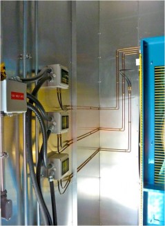
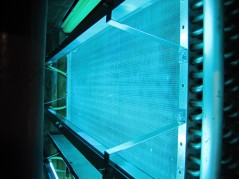
The units are also provided with UV lights for the cooling coils, something the owner feels is essential for minimizing maintenance and operating costs over the life of the units.

 Questions on Custom Air Handling Units:  askRick?
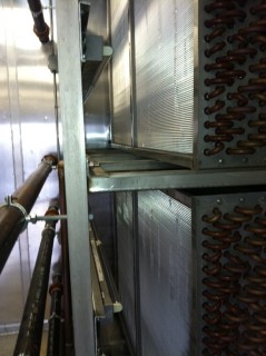
Portland Jet Port - Steril-Aire UVC Install

Portland Jet Port - Steril-Aire UVC Install


Related Blog Posts:
Custom Air Handling Units | 5 Reasons to use Custom Air Handling Units

Project Snapshot: Lawrence Memorial Hospital | Custom Air Handling Unit
Ask Rick: What is UVC?

Q.  What is UVC?

Steril-Aire UVC Install

Steril-Aire UVC Installation

UVC is a type of ultraviolet (UVC) energy in the 260-nanometer frequency.  The “C” wavelength is the most germicidal in the UVC spectrum. UVC penetrates the outer structure of the cell and alters the DNA molecule, preventing replication and causing cell death. The UVC energy kills or inactivates microbes, eradicating surface biofilm.

UV light in the form of germicidal lamps has been used since the late 1800s to kill the types of microorganisms that typically cause indoor air quality (IAQ) problems — bacteria, mold, yeast, and viruses.

The introduction of UVC into HVAC systems is pioneered in 1996 by Steril-Aire of Burbank, California. Steril-Aire’s systems-engineered germicidal UVC Emitters installed in HVAC systems provide a proven and cost-effective tool to reduce energy consumption and operating costs while improving indoor air quality.

Installed at the cooling coil and drain pan in an HVAC system, UVC eliminates surface biofilm — a complex matrix of mold, bacteria, viruses and debris.

Key Benefits:

  • Energy Savings:   Lowers energy costs by improving HVAC system heat transfer and increasing net cooling capacity.  Offers a return on investment in less than 2 years.
  • Maintenance Savings:   Continuously cleans coils, drain pans plenums and ducts, reducing or eliminating manual cleaning and the use of harmful chemicals.
  • Improved IAQ:  Significantly decreases mold, bacteria and virus introduction to supply air stream.
  • Water Conservation:  Reclaiming clean condensate for tower makeup, irrigation or gray water flushing reduces water and waste water costs.
  • LEED Contribution:  UVC may contribute to LEED points in one or more areas.

 If you have questions on UVC,  feel free to;  askRick?

Ask Rick: Fan Array | Does it make sense?

Q.  I have been looking at different fan options for my Air Handling Unit application.  What are your thoughts on the Fan Wall technology?


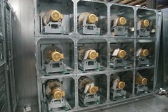
Fan ArrrayThe technology is called by different terms;  Fan Array, Fan Wall, Fan Matrix, Multi-Fan etc.  It is a combination of smaller fans built into a wall section to replace a traditional single large fan.  It was initially developed by Hunt Air and now is available in some form through nearly every air handling unit manufacturer. 

The marketing of this approach listed the following as the key reasons to employ this fan arrangement:

  • Shorter Footprint
  • Quiet Operation
  • Energy Savings through Optimized Performance
  • Redundancy
  • Lower Maintenance Costs
  • Good for Retrofits

Now that we have access to this technology and have used it on several projects we have an opinion. 

Shorter Footprint:  Not really.  In optimal design practice we will use use multiple fans (2 to 4 fans) to help shorten the unit .  With a fan array you can save a couple of extra inches but not much more. 

Quiet Operation:  Yes this can be true, but…….  The fan array is usually quieter because the fans can be provided inside individual acoustical enclosures.  The same type of enclosures can be used with fewer fans (like a 2 to 4 fan arrangement).  The acoustical enclosure decreases sound output and saves having to include a separate acoustical attenuator section.

Energy Savings through Optimized Performance:  Do not agree here.  Larger fans are more efficient than smaller fans, we all know that.  Also,  larger motors are more efficient than smaller motors,  we know that too.  We always opt for the most efficient design which means fewer fans.  The reason we add additional fans is for redundancy.  If you add more fans you pay a premium in efficiency.

Also less efficient motors add more fan-heat and increase cooling requirements. 

Redundancy:  Yes,  the fan array will provide redundancy.  But how much do you need?  We typically provide the minimum amount of redundancy to match system requirements.  If one fan fails you want to satisfy somewhere between 75 and 100% of the capacity with remaining fans (depending on system diversity).  Anything more is really wasteful and not efficient. 

Lower Maintenance Costs:  In a perfect world we would provide equipment with no moving parts,  then nothing would break.  If you have 16 fans instead of 2 fans,  where’s the maintenance savings?  More moving parts (fans and motors) equals more maintenance.  That’s simple to understand.

The argument that it’s easier to change out a motor in a fan array doesn’t make sense.  It’s still really hard to change out a 250 pound 7.5 hp motor.  OSHA will make you use two people and a chain fall (same as with a 650 pound 30 hp motor).  Nobody wants to do either.

Good for Retrofits:  Yes,  We agree with this, but…….   We have done over 100 field erected units in the past 20 years and most have been space constrained.   We have used the fan array in one application.  In that case the extra inches made a difference.   In all others we used 4 or fewer fans. 

So does the fan array make sense?  We don’t think so in most applications.

Additional questions on Air Handling Unit Design;  askRick?

Related Blog Posts:
Custom Air Handling Units | 5 Reasons to use Custom Air Handling Units
Custom Air Handling Unit Design | The ECM Fan Array
VAV Diffusers | Providing Better Individual Temperature Control

Acutherm Therma-Fuser Diffuser – Better Individual Comfort

Making buildings more comfortable places to work.

Therma-Fuser VAV diffusers are ceiling air diffusers with the thermostat and VAV damper built-in. These small zones of control provide individual comfort that precisely match the comfort requirements of the room or portion of the room served.

Therma-Fuser diffusers also provide a constant discharge velocity with comfort benefits of higher throws, no cool air dumping, better room air movement and uniform temperature distribution.

Questions on Acutherm Therma-Fuser Diffusers;  Ask David Goodman

Questions on HVAC design;  askRick?

Related Blog Posts:
VAV Diffusers | New clever design for the Therma-Fuser
Energy Saving VAV Diffusers | 6 Options for Building Automation Systems

Ask Rick: Pumped glycol energy recovery systems | Reasons for poor performance in traditional systems

Q.  You have mentioned that traditional pumped glycol energy recovery systems were your least favorite choice for air-to-air energy recovery.  What are the reasons for that?

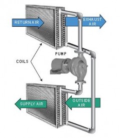
Traditional Pumped Glycol Energy Recovery System

Traditional Pumped Glycol Energy Recovery System

A.  It starts with efficiencies.  Pumped Glycol systems in this country, until the recent introduction of Konvekta, have provided the lowest efficiencies for all choices.  The best we could expect from a system would be 45%.  After subtracting pumping cost,  the efficiencies would drop below 40%.  And that’s the best we could get.  That’s not good compared to 60 to 75% for other types of air-to-air energy recovery (wheels, plates & heat pipes).

Traditional pumped glycol energy recovery systems have also been the most maintenance intensive choice. 

Other common causes for poor performance:

  • Design Issues
    • System is designed for a degree day that never happens
    • Supply and exhaust coil design doesn’t match
    • Single speed pumping system doesn’t match VAV airflow
    • No glycol expansion tank in the system
    • No Deaerator or malfunctioning deaerator 
  • Operating Issues
    • Air volumes don’t match design
    • Running the pump in the ‘dead window’ of temperatures
    • Picking wrong design point to shut system down –  can result in overheating the supply air
    • No system performance verification
  • Maintenance Issues
    • Dirty Coils
    • Air in glycol loop

So why do we use pumped glycol loops?  They my be the most inefficient but are also the most flexible.  When supply and exhaust air streams can’t be run side by side pumped glycol systems are the only choice.  That’s the big reason why they are used.  Most of the pumped glycol run around loops that we have designed over the past 20 years have supplied marginal performance, but it was the best we could get.  Today we use Konvekta systems which provide efficiencies comparable to other devices but also provide system flexibility.

For more information on pumped glycol systems,  askRick?

 Looking for better solutions for pumped glycol;  read these Blog Posts:
Pumped Glycol Energy Recovery | What’s so special about Konvekta?

Pumped Glycol Energy Recovery | Konvekta High Performance Heat Exchanger Coil

Project Snapshot: High Plume Dilution Fans | Odor Control

Project Type: Regional Paper Company
Project Application: Odor Remediation
Equipment: High Plume Dilution Fan
Size: 10,000 CFM at 2.5″ SP
Manufacturer: Strobic Air
DAC Sales Engineer: David Goodman


Project Highlights:             

Strobic Air - Tri-Stack Fan - Dilution Diagram

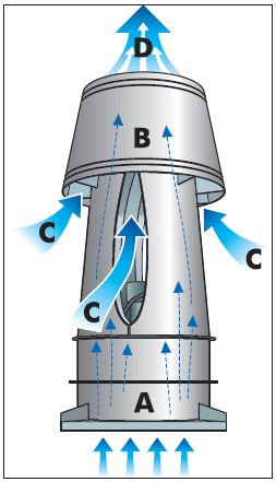
Mixed-flow impeller fans reduce odors through direct dilution.

The Problem:  One of the neighbors on the hill above the paper manufacturing plant claimed to be smelling the chemicals being exhausted from the plant.  While nobody else could detect any odor,  including myself, the neighbor threatened legal action.  Of particular concern was the bleach and sodium bi-sulfate used in tanks to color the paper. Each tank has existing stainless steel duct which runs through the roof to an old belt drive fan set.                                                                                                     

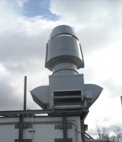
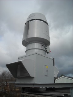
The Solution: Wanting to be a good neighbor,  the paper company took a pro-active approach.  Through internet research of dilution fans the owner found Strobic Air and contacted DAC Sales.  DAC Sales made a visit to the site to review the application.  A single Model TS-3 Tri-Stack high plume dilution fan was selected to provide a dilution ratio of 400 + %.   A corner location of the building was selected to support the fan weight (3,200 #s) and to provide a convenient location for existing duct run into the side of the plenum. 

Strobic Air Tri-Stack Fan - Odor ControlStrobic Air Tri-Stack Fan - Odor Control


Other Features: Sound attenuation was also implemented for this project.  The paper company didn’t want to create a noise problem while correcting for an odor issue.  Therefore an Integral Silencer Nozzle was selected and provided.  To conserve energy, a VFD and bypass air control was provided to manipulate the fans output based on processes and/or prevailing winds.  To facilitate motor change-out, a device was built to facilitate a nozzle and motor removal.  A simple 20 ft long pipe with boom was attached to the structural frame of the system by a hinged plate.  This provided an easy means to lift the motor and drop it to the lower roof level.
Blog Post by David Goodman

Related Case study from Strobic Air:   Mixed Flow Fans for Odor Management

Further questions on High Plume Dilution Fans for Odor Control;  askRick?

Related Blog Posts:
High Plume Dilution Fans | What is a High Plume Dilution Fan?
High Plume Dilution Fans | 3 Key Design Questions

Energy Recovery Wheels | Understanding Cross Contamination / Leakage

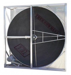
Energy Recovery WheelIn many applications it is important to limit the cross contamination (leakage) from the exhaust to the supply side of an energy recovery wheel.  In some applications, like laboratories, it’s critical.  In other applications, like schools, it’s not a big concern.

There are two ways that air can leak from the exhaust side to the supply side of a wheel:

Cross-Flow Leakage occurs when air leaks from the exhaust side to the supply side through the seals or any gaps in the construction.

  • Select the right equipment. 
    • Use high quality Custom Air Handling Units with  Leakage at no more than 1% of the design volume at 1-1/2 times the design operating pressure. 
    • Use high quality Energy Recovery Wheels with high quality, properly adjusted, seals. 
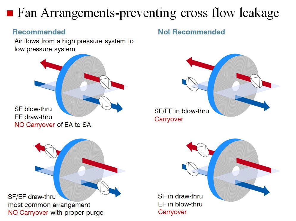
  • Limit Cross Flow Leakage by Proper Fan Arrangement:  Position the Supply Fan in a blow-thru and the Exhaust Fan in a draw-thru position for the safest fan orientation.
Fan Arrangement preventing cross flow leakage

 
Carryover Leakage
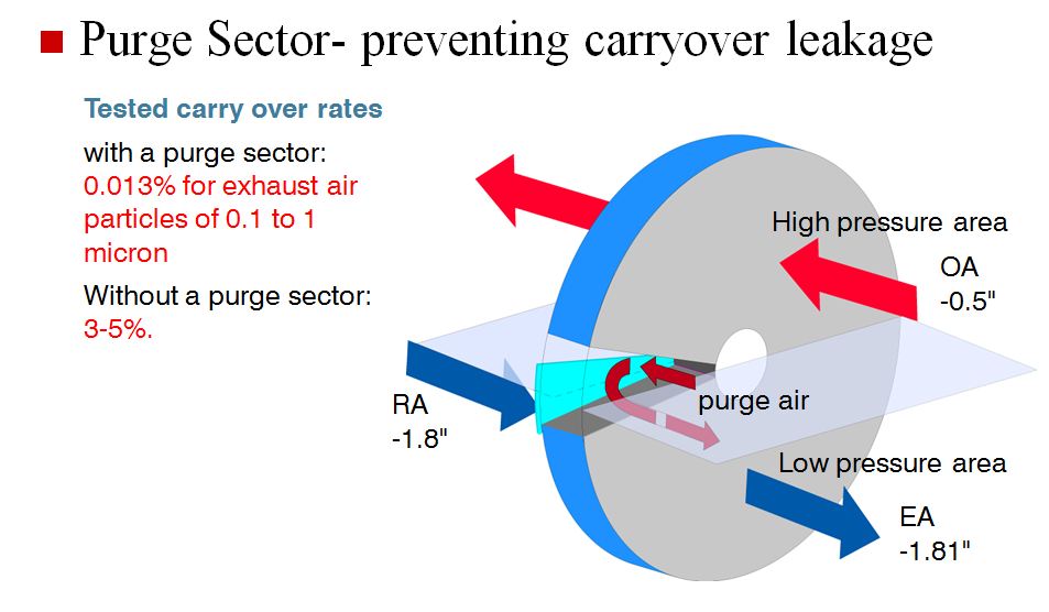
– occurs in rotary recovery wheels  as the wheel rotates from the exhaust to supply air stream.  A small amount of exhaust air can be carried over in the flutes of the wheel as it passes by the center-line seal. 

  • Limit Carryover Leakage with use of a Purge section.  The purge section uses the pressure differential between supply and return to “purge” the media with clean outside air before its rotation into the supply air stream.

 Purge Preventing Carryover Leakage

Note:  The purge comes with a penalty.  Fans typically need to be sized for an additional 5% of air flow.

Cross-Flow and Carryover leakage are two ways air can leak from the exhaust to supply side of an energy recovery wheel section.  It can also leak through other sections or components in the Air Handling Unit.  Choose a high quality Custom Air Handling Unit to avoid this. 

Questions on Energy Recovery Wheels;  askRick?

Related Blog Posts:
Energy Recovery Wheels | What is an Enthalpy Wheel?

Ask Rick: Energy Recovery Wheels on Laboratory Fume Hood Exhaust?
Ask Rick: How much cross contamination occurs with an Energy Recovery Wheel?

Ask Rick: Control for Wrap Around Heat Pipes

Ask Rick Question:  I am considering putting in a wrap around heat pipe to reduce cooling tonnage and provide reheat.  Is there a way that I can control the heat pipe to reduce reheat?


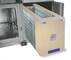
Wrap Around Heat PipeThe Wrap Around Heat Pipe (or Dehumidification Heat Pipe) is used in lots of applications where reheat is typically used.  They are usually applied as passive devices designed to match the system requirements.  Modulation of the cooling coil alone is often adequate for control.  In some instances the need for maximum sensible cooling overrides the need for humidity control.   Because of this, it is necessary to temporarily lower the effectiveness of the heat pipe.  
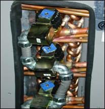
We prefer controlling Wrap Around Heat Pipes with Electrically Operated Solenoid Valves.  The, normally open,  electric solenoid valves are installed in the liquid return lines of the individual heat pipe circuits. The number of valves needed is determined by the size of the heat pipe, the number of rows, and the degree of control desired. 

We don’t typically provide controls for all circuits.  That’s too costly and too large a range of control.  It’s typical to control half the circuits on a dehumidification heat pipe.  So the total heat pipe system would have a mix of controlled and uncontrolled circuits on the heat pipe.

Wrap Around Heat Pipe with Solenoids

Wrap Around Heat Pipe with Solenoids

Other Notes on Applying Solenoid Valve Control:

  • Each control valve is operated by either a 24 VAC or 115 VAC digital output (DO) from The Building Automation System. Valves are usually controlled in ganged stages to provide multi-step operation of the heat pipe.

  • 30 Watts of electrical power is needed to operate each valve

  • The size of the solenoids adds depth to the heat pipe center section.  Make sure to consider this in the system design.

Related Materials:
Wrap Around Heat Pipe Control from Heat Pipe Technology
Heat Pipe Technology – DHP with Solenoids- Specification from Heat Pipe Technology

More questions on controlling wrap around heat pipes;  askRick?

Related Blog Posts: 
Wrap Around Heat Pipe | How does a wrap around heat pipe work?
Heat Pipe for HVAC Systems | Heat Pipe Theory


Project Snapshot: UNH Parsons Hall | Lab Exhaust Fan – Energy Recovery Units


Project Name: University of New Hampshire Parsons Hall Renovation
Architect: Einhorn Yaffee Prescott
Mechanical Engineer: Einhorn Yaffee Prescott
Contractor: Gilbane Building Company
Equipment: High Plume Dilution Fan – Energy Recovery Systems
Manufacturer: Strobic Air / Cambridgeport Air Systems
Size: 5 Ea. Energy Recovery Units – sized from 20,000 CFM to 48,000 CFM
DAC Sales Contact: Jim Shiminski


Project Overview:


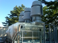
UNH Strobic FansThe University of New Hampshire (UNH) was looking to renovate Parsons Hall, which housed the Chemistry Department and a few related programs.  The renovated facility was designed to accommodate wet teaching laboratories, research labs, the University Instrumentation Center and general classroom space.  It was also to include office space for faculty, researchers, technicians, postdoctoral fellows, and student researchers, as well as common spaces such as a conference rooms and break-out spaces.
 Project Challenges:

  • The renovation schedule for the project included work that was to commence after the UNH graduation in May 2009 and last through 2014.  All equipment was to be prepurchased by Gilbane and coordinated through the life of the project.
  • Energy Savings was key to the project.  All HVAC systems needed to provide optimal energy savings.
  • The fans needed to get lab exhaust up and away from the building.  The exhaust systems were located on the edge of common courtyard area.  Prior fans contributed a great deal of noise to the area.  Sound attenuation was a critical aspect of the design.
  • The fan systems would be visible from several points on the campus.  They needed to be low profile and compact.
UNH Parsons - Heat Recovery PlenumUNH Strobic Fans UNH Parsons - Heat Recovery Plenum


Project Highlights:

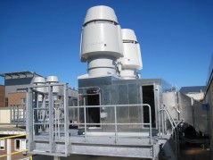
High Plume Dilution Fans from Strobic Air were selected for the project.  Five separate Pumped Glycol Energy Recovery Exhaust Units were designed.  Four of the units had two and one unit had three Strobic Air Tri-Stack Fans.  Each unit had a pumped glycol energy recovery coil (for energy savings) and a filter bank.  Fans were designed to run on VFDs to optimize fan horsepower.  Fans were also designed to stage off to match building load. 

Nozzle Silencer from Strobic Air

Integral Nozzle Silencer from Strobic Air

Integral Nozzle Silencers were included with the Strobic Lab Exhaust Fans for sound attenuation.  The sound data for the  Tri-Stack Fan and nozzle silencers, tested as a complete package,  met or exceeded all site sound criteria.

All Pumped Glycol Energy Recovery Units were designed to be compact and low profile.  Integral Silencers Reduced fan system height.  Energy Recovery Plenum Sections, provided by Cambridgeport Air Systems,  supported the fan systems.  Plenum sections were built with All Aluminum Construction to provide the most sustainable long term solution.  Cost was comparable to painted steel construction and weight savings was about 40%.

See plan highlights on the UNH Project website:  Parsons Hall Renovation

If you have questions about the application,  feel free to askRick?

Related Blog Posts:
High Plume Dilution Fans | What is a High Plume Dilution Fan?
High Plume Dilution Fans | 3 Key Design Questions
High Plume Dilution Fans | Online Selection For Lab Exhaust Fans

Ask Rick: Air to Air Energy Recovery | How to size the energy recovery device?

Q.  I am working on an Air-To-Air Energy Recovery application.  I am thinking of using a wheel or a heat pipe.  I need to know which will fit.  How do you size the energy recovery device for the application?


Energy Recovery WheelA.  There are a variety of energy recovery devices to use for a given application.  Device size can be critical as it usually dictates the size of the Air Handling Unit.  The bigger the device,  the larger the unit dimensions.  Here is a rough guide that we use when starting to look at sizing the different types of energy recovery:
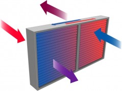
Exchanger Sizing:

  • Fixed Plate Exchanger: design around .75 to 1.25” in. w. pressure drop
  • Heat Pipe: 500 – 600 FPM air flow
  • Pumped Glycol Runaround Loop: 500 FPM air flow
  • Energy Recovery Wheel: 700 – 800 FPM air flow

Heat Pipe Keep in mind that these are starting points for design.  With all devices,  the greater the surface area, the greater the amount of energy recovery.  These starting points consider the most cost effective design point.  In any case where a payback can afford a larger device,  we will use it. 

When considering the use of a wheel or heat pipe there are two other considerations. 

  1. The wheel is a total energy recovery device (sensible & latent transfer) and will provide energy recovery for both summer and winter use.  The heat pipe is a sensible device.  It will offer minimal recovery in summer months.  It’s primary value is gained during winter operations.  
  2. The wheel is in a square cassette.  Some Air Handling Unit configurations cannot be configured to accept a wheel (i.e. unit height restrictions).  In those cases heat pipes can be used.  They can be provided in nearly any length and height combinations.

In recent years we have been designing higher performance air handling units.  In many of these units the energy recovery devices have been increased in size thus lowering the pressure drops and velocities through the devices.  The units are larger and have a higher first cost, but are more efficient and have a lower life cycle cost. 

Further questions on Air-To-Air Energy Recovery;  askRick?

Related Blog Posts:
Energy Recovery Wheels | What is an Enthalpy Wheel?
Heat Pipe for HVAC Systems | Heat Pipe Theory